Maintenance9223−1/A1
RT-flex58T-E
Winterthur Gas & Diesel Ltd.
16/ 22
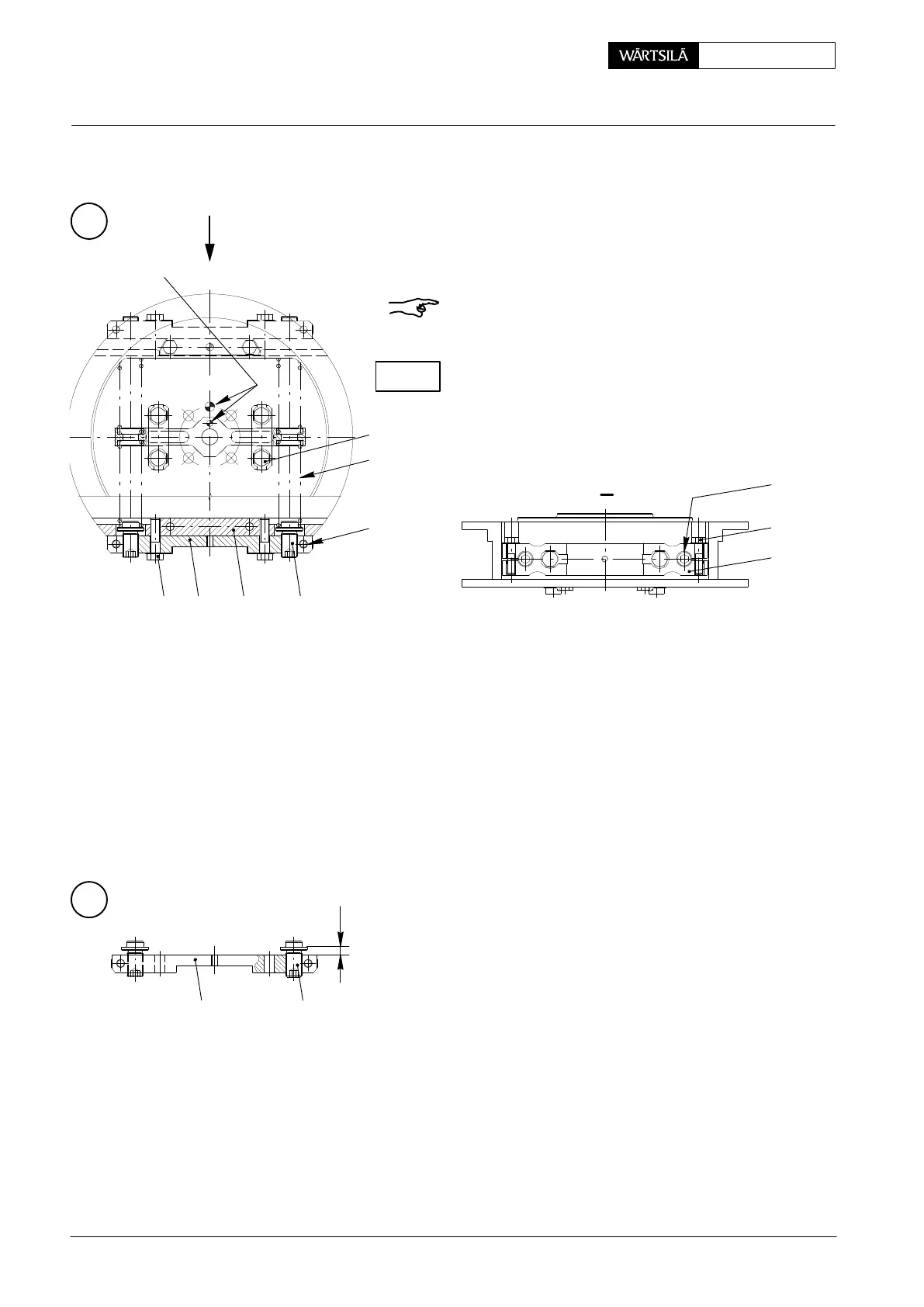
8.4 Fitting the compression spring
⇒ Loosen clamp screws 55 of spring tensioner
52 (Fig. ’X’). Replace locking plates. Apply
MOLYKOTE paste G to threads and seating
surfaces of screws 55 and refit them.
⇒ Oil and adjust all adjusting screws 54 to
’x’ = 10 " 0.10 mm (Fig. ’Y’).
⇒ Insert compression springs 42, fit spring ten-
sioner with screws 53 and new locking plates,
applying MOLYKOTE paste G to threads and
seating surfaces.
⇒ Tighten screws 53 with a torque of 60 Nm and
lock them.
008.751/01
008.750/01
008.749/01
8.2 Removing the compression spring
⇒ Loosen screws 53 and remove them together with
spring tensioner 52.
⇒ Remove and check compression springs.
Remark: When replacing only one compression spring
42, it is recommend to remove also the second spring
tensioner for carrying out further adjustments.
Check spring seating surface for wear.
Y
I
x
54
55
52
5452
X
I
53 52 51 54
55
42
57
FITTING
POSITION
8.3 Fitting of the lever
⇒ When fitting lever 43 pay attention to its fitting position (Fig. ’X’).
⇒ Replace locking plates to screws 57.
⇒ Apply MOLYKOTE paste G to threads and seating surfaces of screws 57.
⇒ Tighten screws 57 with a torque of 60 Nm and lock them.
CHECK
2013
Crank Angle Sensor Unit: Dismantling, Assembling and Adjusting