IB70 Motherboard User Manual
14
2.4 Jumper Settings
This section explains how to set jumpers for correct configuration of the
motherboard.
A pair of needle nose pliers may be helpful when working with jumpers.
If you have any doubts about the best hardware configuration for your
application, contact your local distributor or sales representative before
you make any changes. Generally, you simply need a standard cable to
make most connections.
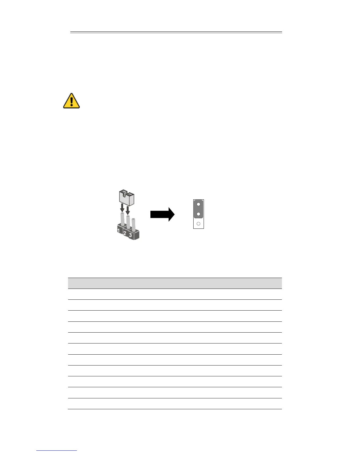
The jumper setting diagram is shown below. When the jumper cap is placed on both
pins, the jumper is SHORT. The illustration below shows a 3-pin jumper; pins 1 and 2
are short. If you remove the jumper cap, the jumper is OPEN.
2.4.1 Jumper List
The following table shows the function of each of the board's jumpers.
Brightness PWM Voltage Selector
Brightness Control Select
Brightness Control To VRD
Serial Port(RS232/422/485)Select
Serial Port(RS232/422/485)Select
VRD Brightness Function Select