8-5
SECTION 8 –
ENTERTAINMENT
4. Press Release Button on the Rotational Knob
and rotate antenna (until maximum number of
LED lights illuminate on the Signal Meter).
NOTE: LED lights will illuminate from left to
right. All LED lights may not illuminate,
depending on signal strength.
5. Rotate Attenuator Dial COUNTER-
CLOCKWISE until the last illuminated LED
light flickers.
6. Rotate antenna to illuminate the last flickering
LED light.
7. Repeat Steps 5 and 6 to pinpoint signal
reception.
NOTE: Refer to television manufacturer’s
instructions to scan for available
channels.
Further Information
See the antenna manufacturer’s user guide
provided in your InfoCase for complete operating
and maintenance information.
TV SIGNAL AMPLIFIER
The TV Signal Amplifier is built into the
antenna and can be turned on or off with a power
switch on the video selection system (located on
a wall near the TV or in the entertainment center
cabinet, depending on model).
An indicator light will glow when the switch
is on and the signal amplifier is active.
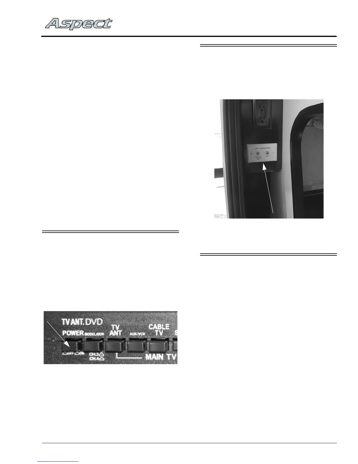
CABLE TV AND SATELLITE
DISH CONNECTIONS
Cable Television and Satellite Dish
connections are provided in the shoreline
compartment.
EXTERIOR CABLE TV - 12V
CONNECTION
–If Equipped
The exterior cable TV/12-volt connection
receptacle on your coach provides connection for
use of a TV and/or 12-volt device for your
outdoor entertainment.
TV Signal Amplifier Switch
(Located on Video Selection System)
Cable TV/Satellite Dish Connections
(Located in backwall compartment)
-Typical installation shown