GMZ-E Operating manual Page 14 of 31 B0668
4.3 Functioning
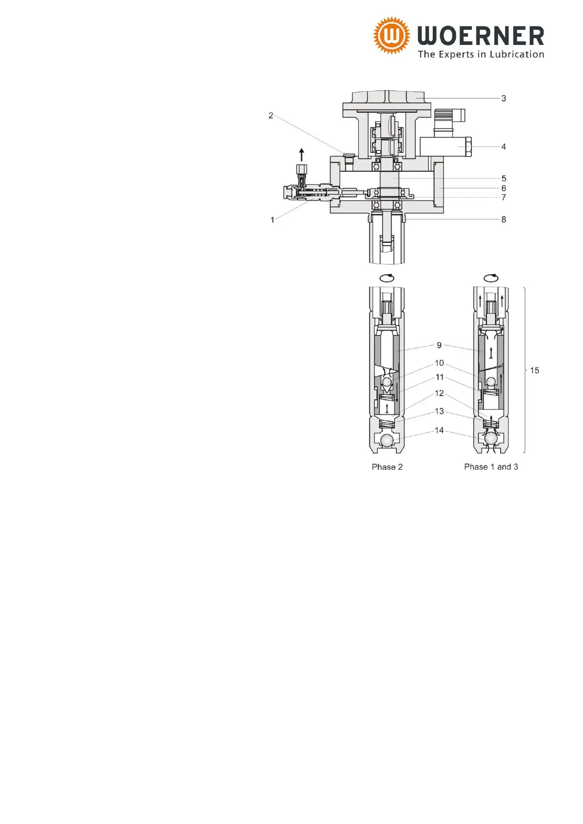
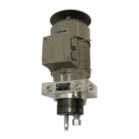
1 Pump element
2 Vent screw G 1/4
3 Gear motor
4 Pressure monitor
5 Eccentric shaft
6 Pump casing
7 Pressure ring
8 Threaded connection G2
9 Control piston
10 Check valve
11 Delivery piston
12 Intermediate chamber
13 Pressure spring
14 Check valve
15 Delivery pump
The barrel pump consists of the
following components:
Feed pump (15), pump housing
(6), pump elements (1) and drive
motor (3). The feed pump (15) is
powered by the drive motor (3)
via the vertical eccentric shaft (5).
Phase 1
During the suction stroke the delivery piston (11) forced downward by the control piston (9) is
pressed upward again by the compression spring (13). The vacuum resulting in the
intermediate chamber (12) causes the lubricant to be drawn in via the non-return valve (14).
Phase 2
During the next half revolution of the control piston (9), the delivery piston (11) is forced
downward again and the lubricant contained in the intermediate chamber (12) is delivered in
upward direction via the nonreturn valve (10).
Phase 3
Further rotation of the control spool (9) through 180° results in a new suction stroke and the
non-return valve (10) closing at the same time enables the spring-loaded delivery piston (11)
to force the lubricant above it into the upper pump housing (6).
The pressure monitor (4) signals "barrel empty" when no more lubricant is delivered by the
feed pump (15), however there is still lubricant left in the pump housing.
The vertical eccentric shaft (5) drives a pressure ring (7) to which the pump elements (1) are
attached. Due to the eccentricity of the pressure ring (7) each delivery piston performs one
constant delivery and suction stroke per pump shaft revolution.
The pump elements (1) draw accurately metered quantities of lubricant (dependent on element
adjustment) from the lubricant reservoir in the pump housing (6).