Cooling
12
9. Electrical supply & function
CAUTION:
Both the condensing unit and evaporator should be fed from the same electrical supply. If this is not possible, it is
important to ensure that the electrical supplies are from the same phase. Failure to do so will result in a potential
of 415 Volts between the units. Always ensure that the electrical supply to the unit is isolated before opening any
panel or carrying out any work on electrical equipment.
Cable sizing
Cable sizes should be selected to suit the application, adhering to the latest IET 18th Addition BS7671:2018 Wiring Regulations.
It is recommended that SWA cable is used with the armor braiding suitably secured in the gland. The cable must also be termina-
ted and earthed correctly at its point of entry into the units. The BMIEP and BMOP unit power connections are suitable for cables
up to 4mm. For cables larger than this it is recommended that the larger incoming cable is terminated at a wall mounted junction
box or isolator close to the unit, and a reduced size cable is used to connect the junction box/isolator to the unit.
Cable connection / termination
There is no interconnecting wiring between the evaporator and condensing unit. They operate independently on a pump down
control system. All Evaporators and Single-phase Condensing units require a Live, Neutral and Earth supply. Three-phase conden-
sing units require a Three-Phase, Neutral and Earth supply. The electrical supply to the unit must be taken from correctly sized
main circuit breakers (motor rated) or fuse boxes, which correspond to the condensing unit, evaporator and evaporator heater
currents. Additional information can be found within this manual under the electrical section of this document.
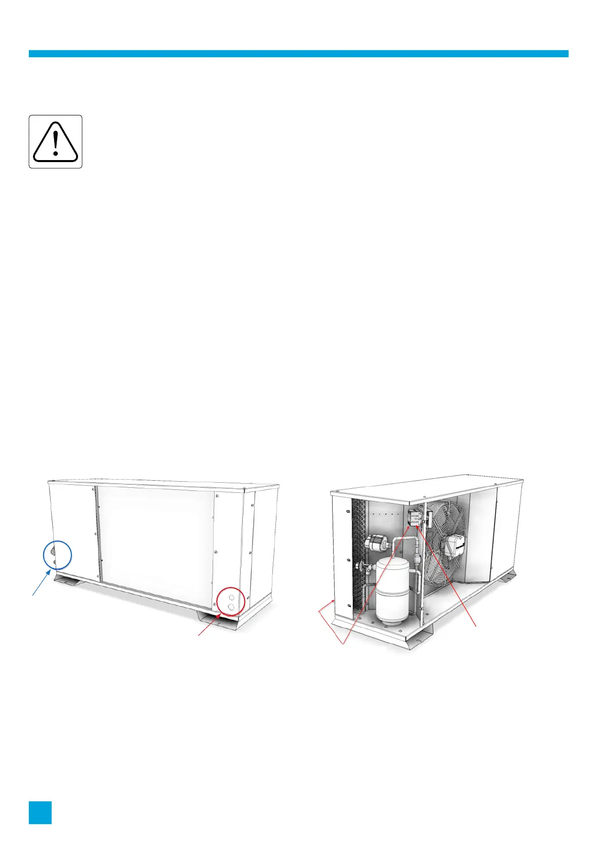
10. Power entry to the condensing units
There are two power entry points marked by the RED circle. The BLUE circle shows the pipe connections.
Ensure any cables are routed clear of the compressor, pipework and crankcase heater to the mains isolator.
Mains Connection
Mains Isolation
Looking at the
back of the unit
Customer
Electrical Entry
Points
Rear of unit