13
Cooling
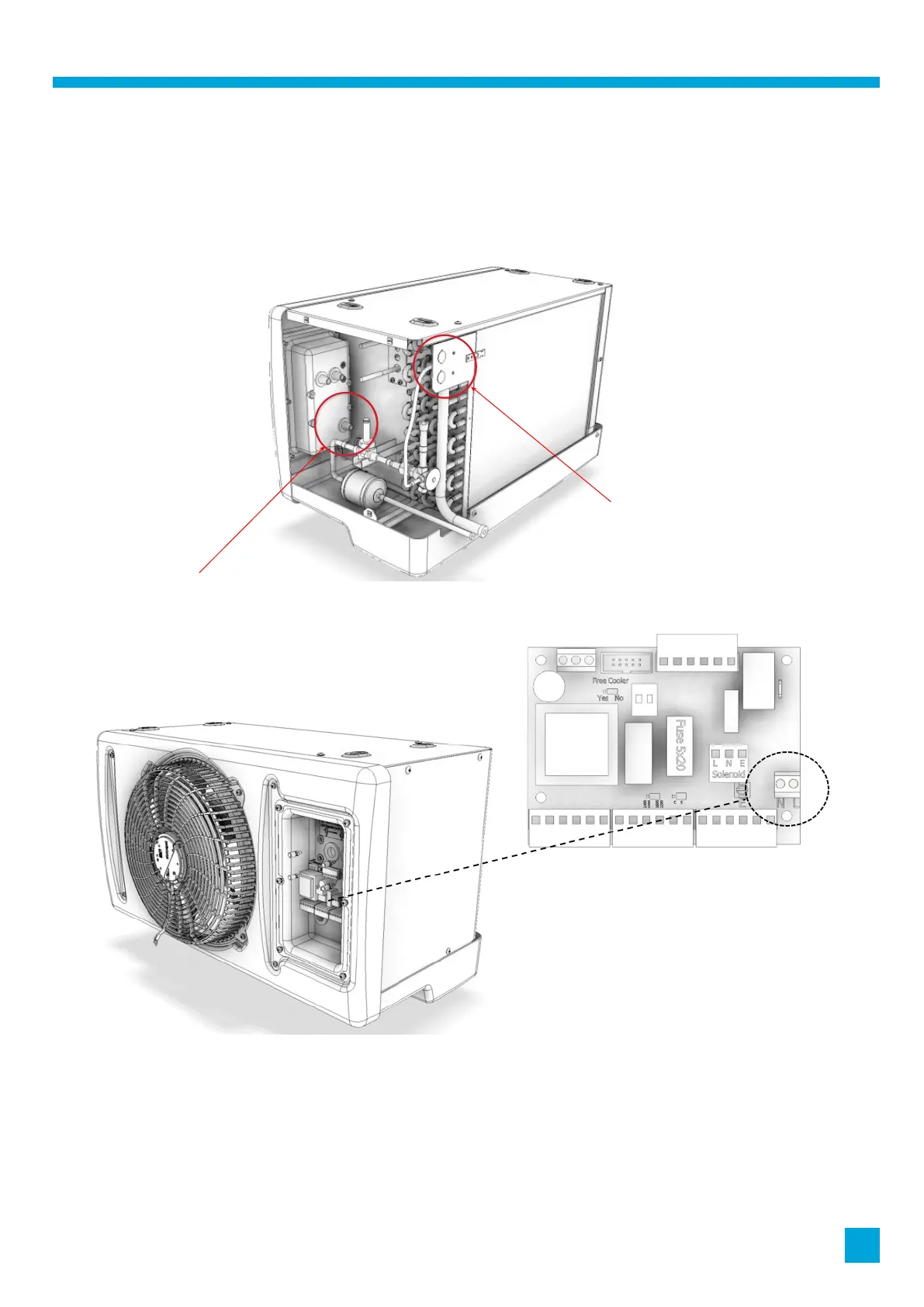
11. Power entry to the evaporators
The power entry points are on the back-left hand side of the evaporator, as shown circled below. The cable should be suitably
secured in a gland and earthed to the stud provided. The supply L & N cable cores should be routed into the control box via the
conical grommet, as shown circled below.
Power entry points
Conical grommet
For access to the control box, the 6 fascia display screws should be removed and the connecting lead to the fascia display should
be carefully disconnected. The supply L & N cores should be connected to the 2-way power terminal on the larger PCB, as shown.