PN-52886 (4/97)10
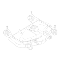
Top Link Attachment (Figure 2)
When the cutting height is adjusted, adjust tractor top
link until mower top link attachment point “A” is
aligned vertically with mower hitch pin “B.”
B
A
1
CD3944
1. Tractor top link
A. Mower top link
attachment point
B. Mower hitch pin
Figure 2. Top Link Adjustment
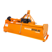
Attaching Mower to Tractor
The standard 1-3/8” 6B spline driveline with a QD
yoke is used to connect mower to tractor.
Attach the mower hitch pins to lower tractor lift arms
and secure. Attach tractor top link (1), Figure 2, to
mower top link bracket attachment point “A.” Connect
the driveline to the tractor PTO shaft and attach tether
chain to tractor drawbar, Figure 3.
WARNING
! Make sure spring-activated locking
pin or collar slides freely and is seated
firmly in tractor PTO spline groove.
Adjust the tractor lower 3-point arm anti-sway devices
to prevent mower from swinging side to side during
transport.
CM906
TETHER CHAIN
Figure 3. Attaching Mower to Tractor
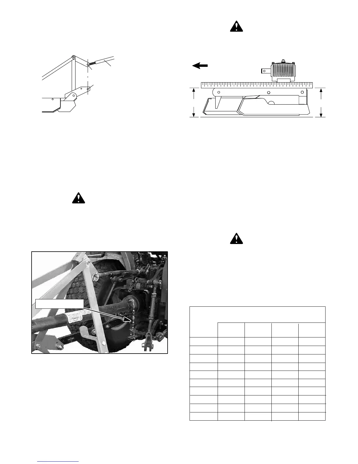
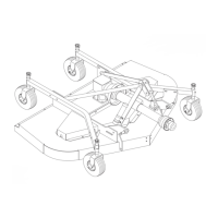
Cutting Height Adjustment (Figure 4)
IMPORTANT
! Avoid low cutting heights. Striking the
ground with blades produces one of the
most damaging shock loads a mower can
encounter. Allowing blades to contact
ground repeatedly will cause damage to
mower and drive.
WARNING
! Keep all persons away from operator
control area while performing adjust-
ments, service or maintenance.
CD3551B
B
A
FORWARD
Figure 4. Cutting Height Adjustment
Level mower from side to side. Check by measuring
from mower frame to the ground at each deck rail.
Verify that the same amount of spacers are under all
caster arms. Loosen cap screws that attach caster
arm assembly to deck. Set mower on the ground.
Retighten cap screws. This equalizes the clearance in
the bolt holes.
Best mowing results will be obtained with front of
mower level with, or slightly lower than, the rear.
Cutting height is controlled with front and rear caster
wheel adjustment.
WARNING
! Before working underneath, carefully
read operator manual instructions , discon-
nect driveline, raise mower, securely block
up all corners with jackstands and check
stability. Secure blocking prevents equip-
ment dropping from hydraulic leak down,
hydraulic system failures, or mechanical
component failures.
Spacers Required
Under Caster Arm Pivot Tube
Approx.
Cutting 1/2” 3/4” 1” 1-1/4”
Height Spacer Spacer Spacer Spring
1”
1-1/2” 1
2” 1
2-1/2” 11
3” 2
3-1/2” 12
4” 111
4-1/2” 1111
5” 121
5-1/2” 1121
CUTTING HEIGHT CHART
(Rev. 2/9/99)