PN-52886 (4/97)16
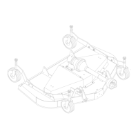
BELT REPLACEMENT (Figure 10)
CD4989VAR
G
B
A
C
D
F
E
1/8″
H
I
IDLER ARM PIVOT
Figure 10. Belt Routing
One of the major causes of belt failure is improper
installation. Before a new belt is installed, check
pulley shafts and bearings for wear. Check pulley
grooves for cleanliness. Make sure spindles turn
freely and without wobble. If grooves require cleaning,
moisten a cloth with a non-flammable, non-toxic
degreasing agent or commercial detergent and water.
Avoid excessive force during installation. Do not use
tools to pry belt into pulley groove. Do not roll belt over
pulleys to install. This can cause hidden damage and
premature belt failure.
IMPORTANT
! Use care when installing or removing
belt from spring-loaded idler at step 5.
Springs store energy when extended and,
if released suddenly, can cause personal
injury.
1. Disconnect idler spring from deck lug “I”.
2. Slide belt underdrive pulley “A”andoveridlerarm.
Position belt around drive pulley “A”.
3. Loosen bolt holding belt guide “G” and swing it
awayfrompulley “B”.Routebelt aroundpulley“B”,
idler “C” and pulley “D” as shown.
4. Make sure belt is on drive pulley “A”, route around
idler“F”,andconnectidlerspringtolug“I” ondeck.
5. Grasp belt between spindle pulley “E”, spring
loaded idler “F” and spindle pulley “D”. Pull spring
loaded idler with belt to obtain enough belt length
torouteitoverpulley“C”.Makesurespring-loaded
idler pivots freely with belt installed.
6. Adjust belt guide “G” to provide 1/16” to 1/8”
clearance from belt. Tighten bolt to 85 lbs.-ft.
BLADE SERVICING
Inspect blades for condition and proper installation each
time before operation. Replace any blade that is bent,
excessively nicked, worn or has any other damage.
Small nicks can be ground out when sharpening.
WARNING
! Before dismounting tractor or perform-
ing any serv ic e or maintenance, disengage
powerto implement, lowerthe 3-pointhitch
and all rais ed components to the ground,
operate valve levers to release any hydrau-
licpressure,setparking brake, stopengine,
remove key, and unfasten seat belt.
! Keep all persons away from operator
control area while performing adjust-
ments, service or maintenance.
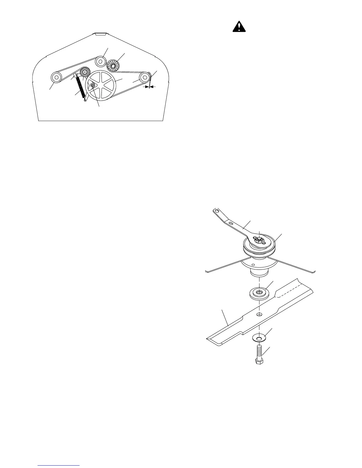
Blade Removal
RD6000 (Figure 11)
Remove belt shields.
Install spindle lock wrench (1) onto spindle pulley as
shown. Remove cap screw (6) which has RIGHT HAND
THREADS. Remove cup washer (5) and blade (4).
Shoulder washer (3) will not normally come off unless
intentionally removed.
CD4988A
1
2
3
4
5
6
1. Spindle wrench
2. Pulley
3. Shoulder washer
4. Blade
5. 5/8 x 3 Cup washer
6. 5/8 NC x 3-1/2” Hex head cap screw GR5
(RD6000)
Figure 11. Blade Installation for
RD6000 SN 793923 and prior
(Rev. 6/28/01)