PN-52886 (4/97)18
DEALER SERVICE
The information in this section is written for dealer
service personnel. The repair described herein
requires special skills and tools. If your shop is not
properly equipped or your mechanics are not properly
trained in this type of repair, you may be time and
money ahead to replace complete assemblies.
WARNING
! Before working underneath, carefully
read operator manual instructions , discon-
nect driveline, raise mower, securely block
up all corners with jackstands and check
stability. Secure blocking prevents equip-
ment dropping from hydraulic leak down,
hydraulic system failures, or mechanical
component failures.
! Keep all persons away from operator
control area while performing adjust-
ments, service or maintenance.
CAUTION
! Always wear relatively tight and belted
clothing to avoid entanglement in moving
parts. Wear sturdy, rough-soled work
shoes and protective equipment for eyes,
hair, hands, hearing and head.
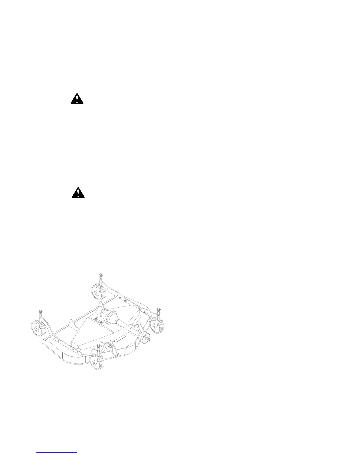
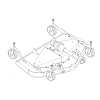
BLOCKING METHOD
(Figure 14)
CD4985VAR
X
X
X
X
Figure 14. Blocking Method
Do not work underneath mower unless it is properly
attached to the tractor and blocked securely. When
properly attached, the unit will be anchored to
minimize front to rear movement.
Raise mower completely, set tractor brakes, turn
engine off, remove key, block tractor wheels front and
rear, and disconnect mower driveline from tractor.
The only approved blocking device for this mower is
a jackstand with a load ratingof 1000 pounds or more.
Install one jackstand under each corner of the mower
(four total), before working underneath this unit.
When blocking, you must consider overall stability of
the unit. Just blocking under the unit will not ensure
your safety. The working surface must be level and
solid to support the loaded weight of the jackstands.
Test jackstands stability before working under any
portion of the mower.
BLADE SPINDLE REPAIR
Spindle repair requires special skills and tools. If your
shop is not properly equipped or your mechanics are
not trained in this type of repair, you may be time and
money ahead to use a new spindle assembly.
For reference, the grease fitting is in the top of the
spindle shaft.
Permatex 3D Aviation Form-A-Gasket
or equivalent
is recommended as a sealant.
Spindle Removal
Remove blade from spindle.
Remove belt from pulleys.
Remove jam nut and washers from top of spindle
shaft.
Disassemble split taper bushing (located on top of
pulley) by removing the two bolts and inserting them
into the threaded holes of bushing flange. Tighten
them alternately to remove split taper bushing.
Remove pulley.
Spindle Disassembly (Figure 15)
Remove bolts attaching spindle to mower frame and
remove spindle.
Remove grease fitting.
Place spindle assembly in press and press shaft
down through housing.
Remove seals from housing.
Remove bearing cups from housing by placing a
punch in slots provided and driving out. Alternate
punch positions from side to side. Take care to
prevent housing damage.
Permatex 3D Aviation Form-A-Gasket is a registered
trademark o f the Permatex Corporation.