PN-52886 (4/97)30
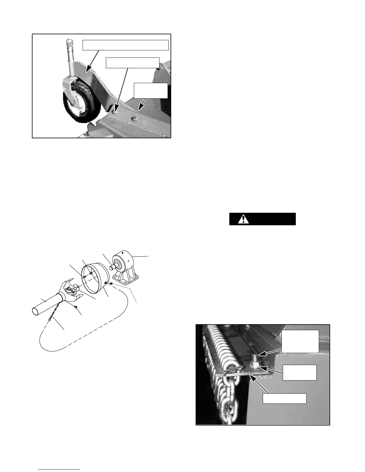
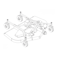
Rear Caster Wheel Installation (Figure 30)
CM850
1/2”
LOCKNUT
CASTER WHEEL ASSEMBLY
1/2 x 1-3/4” BOLT
Figure 30. Rear Caster Wheel Assembly
Remove rear caster wheel assembly from shipping
position and install as shown in Figure 30 using the
same bolts and nuts. Repeat for opposite side.
Tighten bolts so that caster arm is snug against deck
bracket, but not fully torqued.
Refer to Figure 5 on page 11 for possible front caster
arm positions. Attach front caster arm in desired
position and tighten snug against deck bracket.
Driveline Shield Installation
(Figure 31)
CD5064
9
8
7
6
5
4
3
2
1
1. Driveline
2. QD Yoke
3. 8mm x 1.25P x 16mm Hex head cap screw
GR8.8
4. 5/16” Standard flat washer
5. Counter cone shield
6. Gearbox input shaft
7. Anti-rotation chain
8. Shield retainer
9. Gearbox
Chain
Attachment Lug
Figure 31. Rear Driveshaft Installation
The counter-cone drive shield is factory installed on
models RD6000 and RD7200.
On the RD8400 model, attach counter-cone shield (5)
to gearbox (9) with cap screws (3) and flat washers
(4). Orient chain attachment lug as shown.
Driveshaft Installation (Figure 31)
Slide QD yoke (2) of driveshaft assembly onto
gearbox shaft (6). Make sure QD yoke pin is seated
securely in groove of gearbox shaft.
Attach shield anti-rotation chain (7) to drive shield (5)
as shown.
Lift mower off shipping pallet and set on a hard level
surface. This allows clearance in the caster wheel
assemblies to be equalized. Ti ghten all capscrews
and nuts on all four caster wheel arms.
Tighten all capscrews and nuts to specifications found
in Bolt Torque Chart, page 3.
Chain Shielding Installation (Figure 32)
DANGER
! When this equipment is operated inpop-
ulated areas or other areas where thrown
objectscould injure persons or property, full
chainorrubber shielding (which is designed
to reduce the possibility of thrown objects)
must be installed. If this machine is not
equipped with full chain or rubber shielding,
operation must be stopped when anyone
comes within several hundred feet.
Install chain shielding plate to rear mower frame as
shown with carriage bolts inserted from bottom
upward and secured with locknuts.
3/8 x 1”
CARRIAGE
BOLT
3/8”
LOCKNUT
CHAIN PLATE
CM768
Figure 32. Chain Shielding Installation