11PN-52886 (4/97)
To raise rear of mower, move caster adjustment
spacers under caster arms.
To raise front of mower, move spacers under front
caster wheel arms.
Remember, measurement at location “A” Figure 4
should not be less than location “B” and should not be
over 1/2” greater than location “B.”
Tractor Top Link Adjustment (Figure 6)
Adjust tractor top link so mower is level at 16” between
caster wheel and ground (dimension “C” Figure 6).
This will allow the mower to follow ground contour.
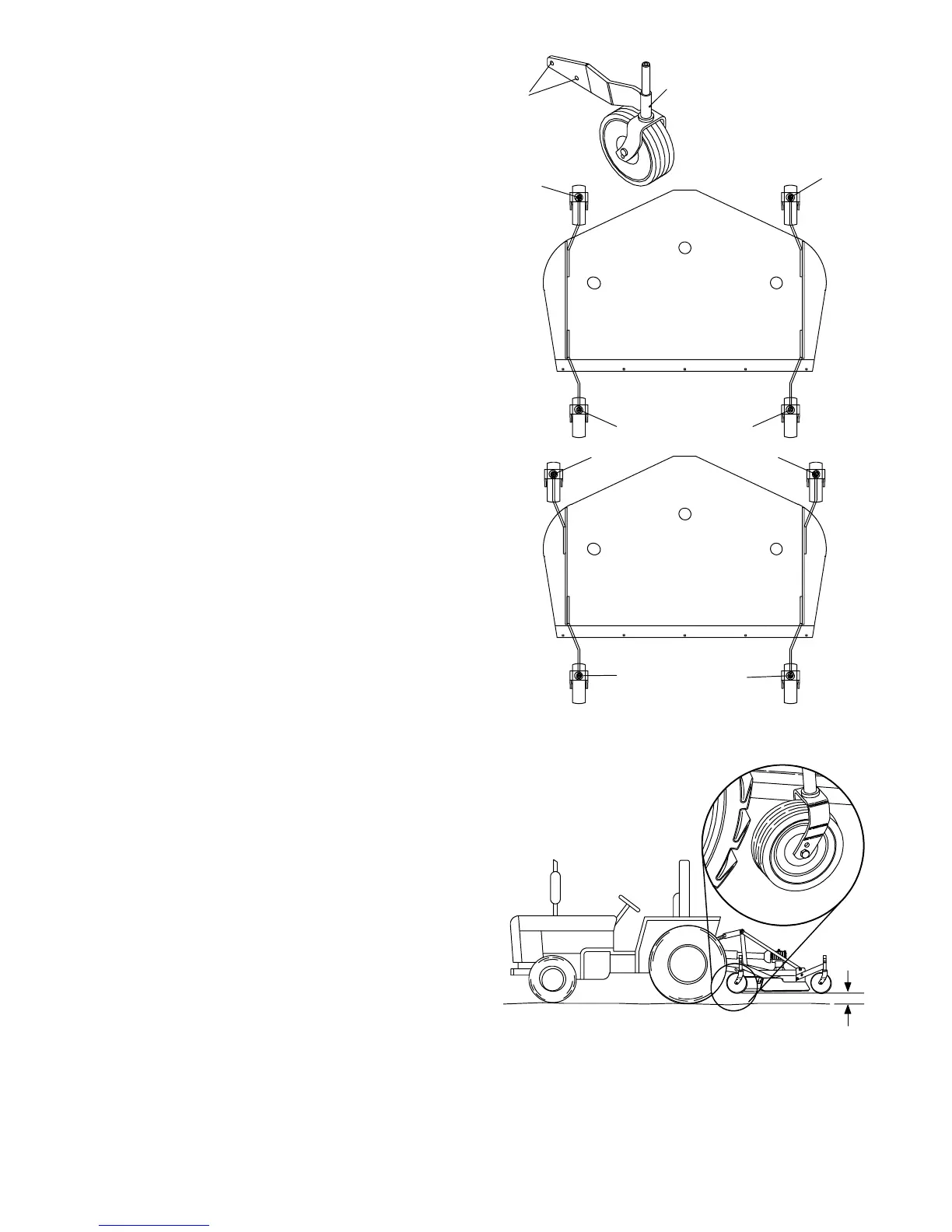
Front Caster Arm Configuration
for RD6000 & RD7200 Only (Figure 5)
The RD6000 and RD7200 front casters can be set in
two positions. This is accomplished using right and
left offset caster arms. The figure shows a right offset
assembly. The direction of the offset is defined by
looking from the mounting hole “A” towards the pivot
tube “B.” The pivot tube should be higher than the
mounting holes. When viewing the arm in this way, the
direction of the offset can be determined.
Figure 5 shows the two possible configurations for the
RD6000 and RD7200 front caster arms. The inner
position allows the outside edge of the mower to be
used for trimming under items such as shrubs or
fences. The outer position provides the most clear-
ance for rear tractor tire interference. To change
configurations, remove the cap screws and nuts and
move the arms from one side of the machine to the
other. Secure with hardware.
The rear caster arms should be mounted as shown.
The RD8400 front caster arms are fixed and cannot
be changed.
Front Caster Wheel Interference Check
(Figure 6)
IMPORTANT
! Do not operate tractor and moweruntil
this interference check has been per-
formed. If you change tractors, you must
perform the check for that mounting.
Perform this check with all of the spacers and springs
above the caster wheel arm. This will place the caster
wheels in their highest position and provide the lowest
cutting height for the mower.
Raise mower with tractor hydraulics to 16” at
dimension “C” or maximum height of tractor lift,
whichever is less.
Pivot both front caster wheels forward and check that
there is clearance between caster wheels and tractor
tires.
CD4990
R
L
L
R
L
R
L
R
A
B
RIGHT
OFFSET
R -- RIGHT OFFSET
L -- LEFT OFFSET
A -- MOUNTING
HOLES
B--PIVOTTUBE
Figure 5. Front Caster Arm Configuration
for RD6000 & RD7200 Only
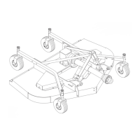
“C”
CD3528C
Figure 6. Front Gauge Wheel Interference Check
If there is interference, on models RD6000 and
RD7200, mount front casters in the outer position. On
model RD8400, caster wheel width is not adjustable;
see tractor operator’s manual and adjust tractor
wheels to narrower spacing.
(Rev. 2/9/99)