Installation
6 720 811 922 (2014/07)20
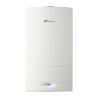
Fig. 23 Mounting template
▶ Remove the mounting template.
▶ Fit wall plugs and secure the mounting plate with appropriate fittings
for the boiler weight and wall type.
▶ Fit the wall plugs and secure the plumbing manifold with appropriate
fittings.
4.3 PRE-PLUMBING THE BOILER CONNECTIONS
▶ Remove the fittings on the connecting pipes.
GAS AND WATER CONNECTIONS - ISOLATING VALVE BRACKET
▶ Ensure that the fibre washers, supplied in the literature/hardware,
are fitted to the connections to the isolating valves.
▶ Ensure that the bonded washer is fitted to the gas pipe isolating valve
connection.
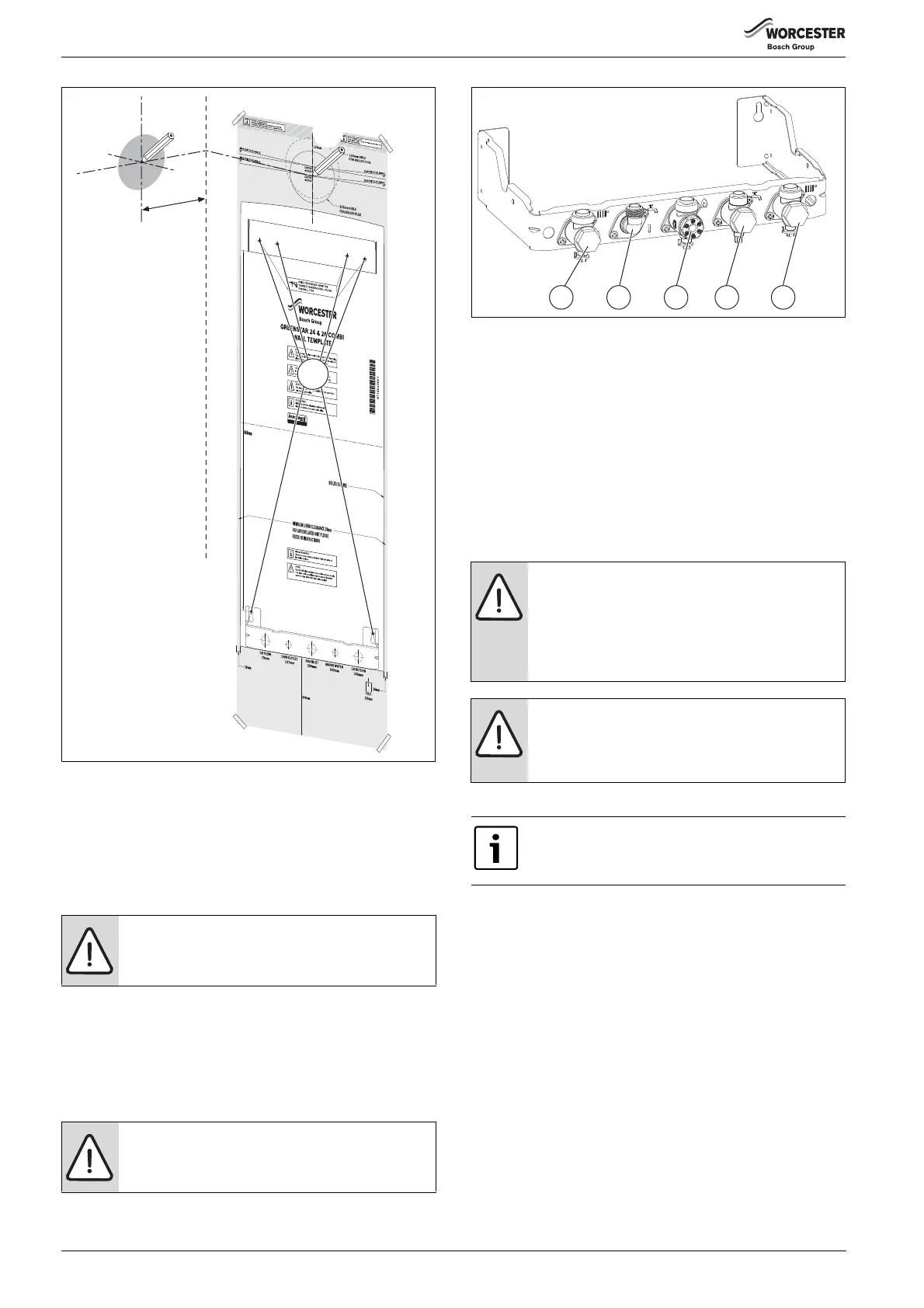
Fig. 24 Isolation valves
[1] CH flow 22mm
[2] DHW Outlet (15mm)
[3] Gas inlet (22mm bonded washer)
[4] Domestic cold water inlet (15mm)
[5] CH return 22mm
▶ All pipe connections in the heating system must be suitable for a
pressure of 3 bar and for 10 bar in a hot water DHW circuit.
▶ For filling and draining the system, fit drain valves at the lowest point
of the system.
▶ Fit an air vent valve at the highest point.
4.4 HANGING THE BOILER
REMOVING THE OUTER CASING
1. Remove the two securing screws underneath the appliance.
2. Slide outer casing from the bottom forwards and lift.
NOTICE: The appliance can be damaged by debris in the
pipework.
▶ Flush the system to remove all debris/residue.
WARNING: Bonded washer for gas (3)
▶ The bonded washer must be used on the gas pipe
isolating valve connection.
4.
1.
3.
2.
218 mm
6 720 811 922-05.1O
CAUTION: Lifting the boiler.
▶ There are two handling holes incorporated into the
inner casing left and right in the lower section of the
appliance.
▶ Do not lift the boiler using the control panel as a hand
hold.
NOTICE: Hanging the boiler.
▶ Remove the plastic strip fitted to pipes before
hanging the boiler.
Please protect the floor from residual water.
The outer casing is secured against unauthorised
removal by two screws (electrical safety).
▶ Always secure the outer casing with these screws.
6720800945-08.1Wo
1 2 3 4 5
 Loading...