Electrical
6 720 811 922 (2014/07) 25
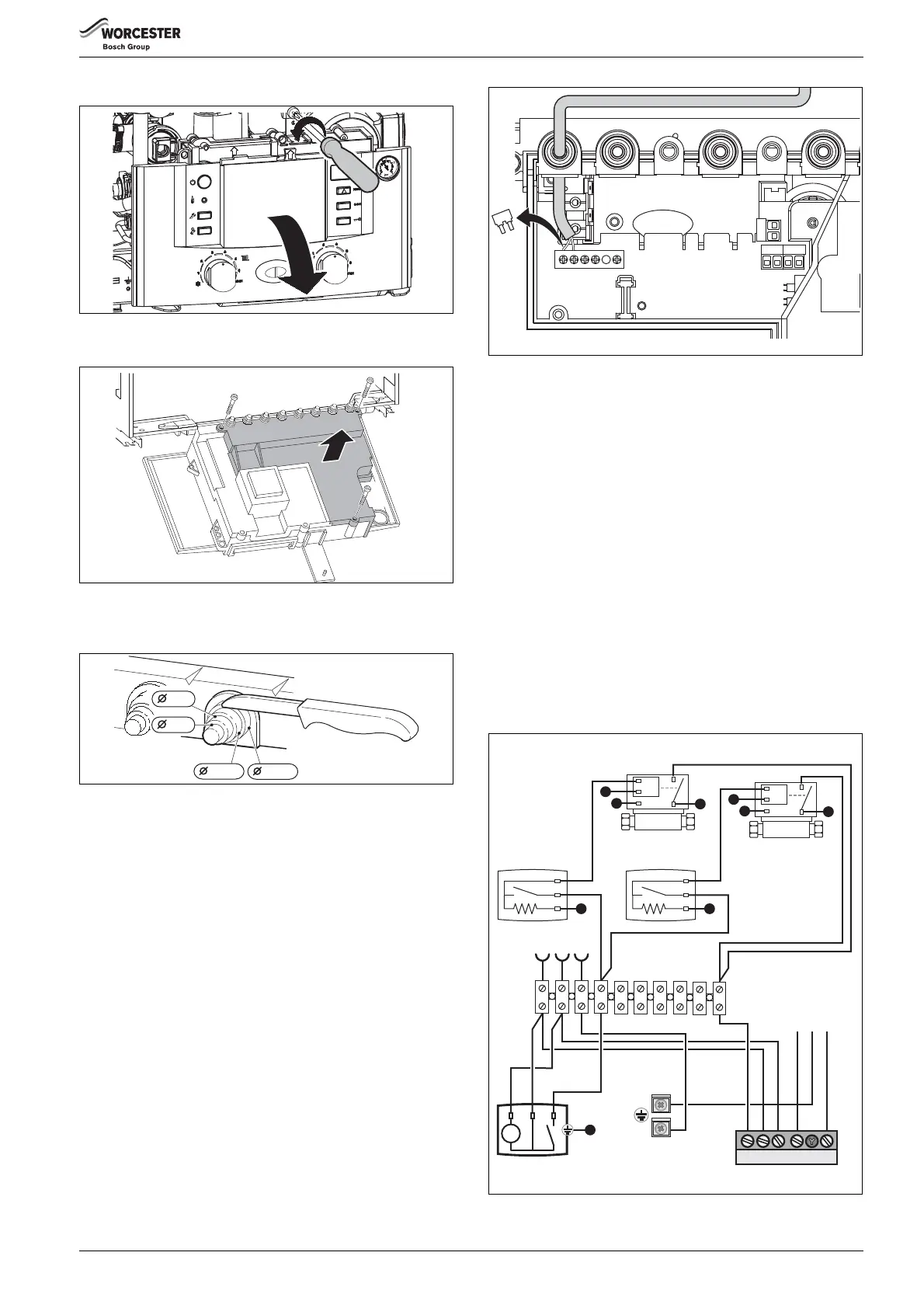
▶ Undo the screw and pivot the control box down.
Fig. 38 Control panel to service position
▶ Remove screws, unhook cable and remove cover.
Fig. 39 Remove cover
▶ To provide anti-splash protection (IP), always cut cable grommet to
fit cable diameter.
Fig. 40 Cut grommet to size
▶ Feed cable through cable grommet and connect as appropriate.
▶ Secure cable in cable grommet by means of a strain relief fitting.
5.3.1 MOUNTING OPTIONAL PLUG-IN CONTROLS
Worcester provides a range of optional plug-in controls with fitting
instructions supplied with the accessories.
CONNECTING A 230 VOLT ON/OFF CONTROLLER
The controller must be suitable for mains voltage (from boiler) and must
not have its own earth connection.
▶ Cut cable grommet to suit the cable diameter
▶ Feed cable through cable grommet and connect programmer to
ST10 as follows:
– L to L
s
– S to L
R
▶ Secure cable in cable grommet by means of a strain relief fitting.
Fig. 41 Connection (230 V AC, remove jumper LS & LR)
5.3.2 NEW COMPLETE SYSTEM INSTALLATIONS
If a new complete heating system is installed in a new build property or it
is a first time installation in an existing property, the heating systems
must conform to current building regulations Part L1a.
All new heating systems in dwellings must have at least two heating
zones. Each of these zones will be controlled by a thermostat and zone
valve.
The exception to this are single storey, open plan dwellings where the
living area is more than 70% of the total useable floor area. Then this
type of dwelling can be controlled as one zone.
An alternative would be individual electronically controlled TRVs.
For dwellings with a floor area over 150m2 a separate time and
temperature control for each zone is required. All radiators must have
TRVs fitted in all rooms except bathrooms and rooms with thermostats.
Figures 51 and 52 give some suggestions regarding zoning the system
for a small dwelling, less than 150m2 floor area, using a third party
programmer or a Worcester programmer.
THIRD PARTY EXTERNAL TIMERS AND TWO ZONES
Fig. 42 Two room thermostats, one external timer
1.
1.
1.
2.
6 720 612 659-15.1R
ST10
LNE4
56
78
910
E
N
L
6720643895-123.1Wo
N
Zone 1
Room Thermostat
N
Zone 2
Room Thermostat
M
~
L
N
E
Zone 1
Zone Valve
M
~
L
N
E
Zone 2
Zone Valve
CH ON
Programmer
L
N
S
N
L
SLR
N
blue
brown
green/yellow
E
230V
MAINS
SUPPLY
L
M
E
 Loading...