Installation
6 720 811 922 (2014/07) 23
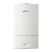
Fig. 33 Flue retaining holes
1. Use the screws provided to secure the flue turret to the appliance.
▶ Fit the screws , from the literature pack to secure flue turret.
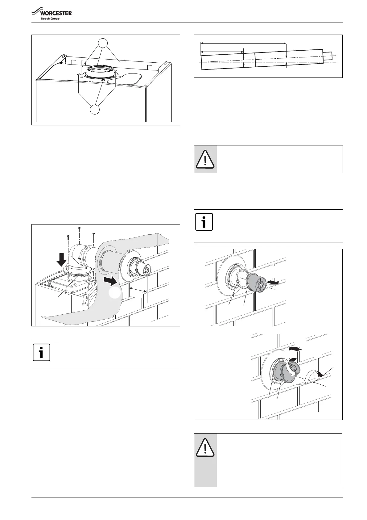
2. Check the boiler flue seal is correctly seated and apply silicone
grease.
3. Position terminal through the flue opening in the wall to the outside
of the building by the distance shown.
4. Align the flue turret to the boiler flue outlet with flat facing to the rear
of the boiler.
The flue turret should be pushed straight down, on to the boiler.
▶ If fitting the outer seal from outside the building, slide the outer wall
seal onto the terminal as shown.
Fig. 34 Telescopic flue installation
ADDITIONAL NOTES AND REMINDERS:
• Ensure that all cut lengths are square and free from burrs.
• The flue is sealed when assembled correctly and the components are
pushed fully home.
• The flue is set at an angle of 3° or 52mm per metre length.
• Support the flue at approximately one metre intervals and at a
change of direction, use suitable brackets and fittings
(Flue brackets 100mm x 6 part number: 7 716 191 173, Flue
bracket 125mm part number :7 716 191 174)
Fig. 35 Slope for condensate disposal
4.5.4 FLUE TERMINAL PLUME RE-DIRECTION:
The flue discharge can be re-directed allowing some plume redirection
control, alternatively, a complete plume management system can be
fitted to the flue terminal.
RE-DIRECTING THE FLUE DISCHARGE
1. Using a suitable tool, unclip (1 & 2) the terminal end and rotate
through 180°.
1. Refit to the terminal, ensuring that the clips (1 & 2) are engaged and
secure.
2. Loosen screws (3) and rotate the entire outlet assembly to redirect
the plume. Tighten screws (3) to secure in the required position.
Fig. 36 Plume redirection
For more information refer to the 60/100 Horizontal
Flue kit Instruction Manual
1.
1.
1.
2.
6720643895-33.1Wo
3.
4.
110
NOTICE: DO NOT rotate the complete terminal
assembly.
The flue terminal outlet has built-in stops to limit rotation
for horizontal fluing to allow condensate to run back into
the boiler for safe disposal. Do not attempt to force
beyond the limit stops.
NOTICE: Outlet position
▶ The flue terminal outlet position must follow those
stated in the relevant appliance instruction manual.
When redirecting the flue discharge the outlet
terminal must be at least 1500mm from any opening
in the direction of the discharge to prevent
combustion products from entering the building.
6720644842-10.1Wo
2m
1m
52mm
104mm
1
2
1.
3.
2.
3
1
±80°
180°
6720643895-34.1Wo
 Loading...