Installation
6 720 811 922 (2014/07) 21
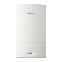
Fig. 25 Removing outer case
▶ Ensure that the sealing washers on the mounting plate connections.
▶ Locate the appliance on the top wall hanging plate.
Fig. 26 Locating the appliance on the hooks
▶ Ensure that the gas and water connections to the isolating valves are
made using the fibre washers supplied in the Literature/Hardware
pack.
PRV CONNECTION
Use the supplied quick connector to connect the copper PRV pipe to the
outlet pipe.
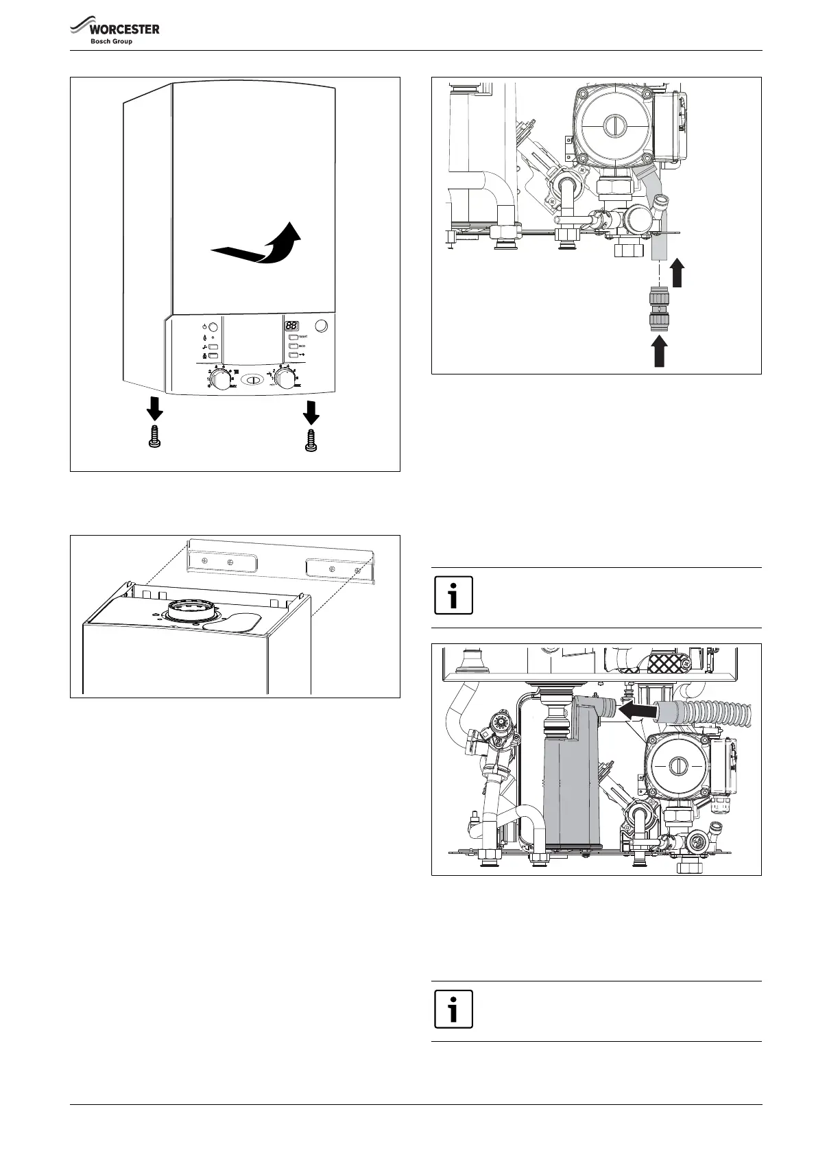
Fig. 27 PRV Connection
CONNECTING THE CONDENSATE TRAP
▶ Remove red blanking cap on condensate drain.
▶ Remove the grey condensate hose from the combustion chamber
during unpacking.
▶ Fit the grey condensate hose onto the condensate trap and route the
hose through the rear and bottom of the appliance ensuring a
constant fall from the trap outlet to the pipework connection.
▶ Check the hose is securely fit onto the trap.
▶ Make connection to condensate drain pipework with adaptor
(supplied in the Literature Pack).
Fig. 28 Fitting the condensate hose
4.5 FLUE INSTALLATION
HORIZONTAL FLUE (60/100mm diameter)
For vertical flues and 80/125mm horizontal flues, please refer to
separate instructions supplied with the flue kit.
Basic instructions for the 60/100mm diameter flue are shown below.
6 720 614 156-03.1O
1.
2.
1.
6720800945-05.1Wo
The grey condensate hose can be reduced in length as
required.
To ease assembly of flue components, apply silicone
lubricant to sealing surfaces.
 Loading...