Commissioning
6 720 811 922 (2014/07)30
6.5 SWITCHING THE APPLIANCE ON/OFF
SWITCHING ON
▶ Switch appliance on at the ON/OFF switch.
The display indicates the current heating water flow temperature.
The indicator for burner operation/faults is permanently on, as long
as the burner is operational.
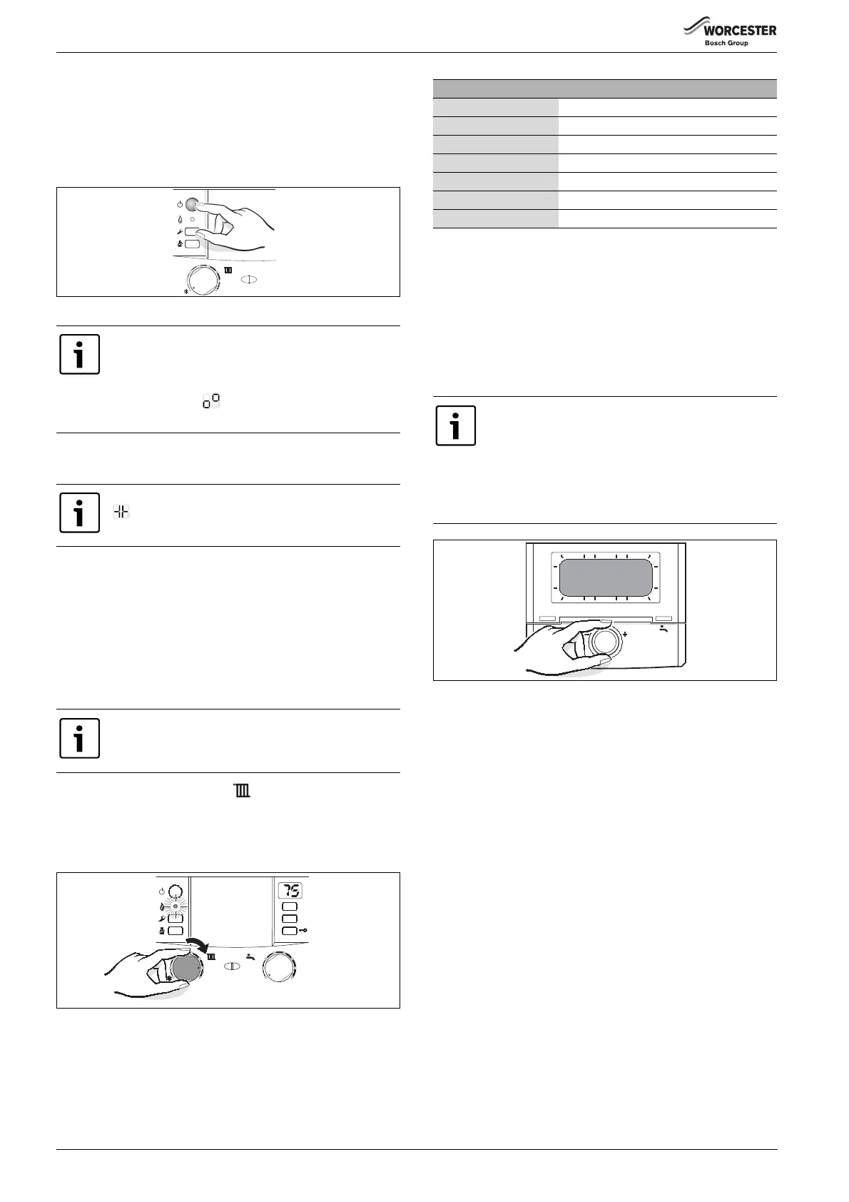
Fig. 48
▶ Open the automatic air vent valve [9] and close it again when the
venting sequence has finished ( page 29).
SWITCHING OFF THE APPLIANCE
▶ Switch appliance off at the ON/OFF switch.
The display goes blank.
▶ If the appliance is to be switched off for a longer period of time:
observe correct frost protection procedures ( Section 6.13).
6.6 STARTING THE CENTRAL HEATING
The maximum flow temperature can be set to between 35 °C and
approx. 90 °C .
▶ Turn CH flow temperature control to adjust the maximum CH flow
temperature according to the central heating system:
– Underfloor heating: e.g. position 3 (approx. 50 °C)
– Low temperature heating system: position 6 (approx. 75 °C)
– Heating system for flow temperatures up to 90 °C: max position
Fig. 49
When the burner is alight, the green lamp for burner operation lights
up.
6.7 SETTING LOW NOx HEATING OUTPUT
Refer to section 7.3.1 on page 35 to adjust the Central Heating output
down from the maximum of 76%.
Enter parameter 53 (53%) and save to set the boiler to low NOx output.
Parameter 53 equates to 53% of the full boiler output which is
approximately 14.15 kW.
6.8 HEATING CONTROL
Fig. 50
When the appliance is switched on for the first time, it
performs a once-only venting sequence. This involves
the heating circuit pump switching on and off at intervals
(for a period of approx. 4 minutes).
The display shows alternating with the flow
temperature.
The syphon filling function is active if the display shows
alternating with the flow temperature, ( page 36).
With underfloor heating systems, take care to observe
the maximum permissible CH flow temperatures.
max
1
2
3
4
5
6
6 720 613 896-05.1O
eco
reset
6 720 615 065-12.1O
max
1
2
3
4
5
6
max
1
2
3
4
e
6
min
Position CH flow temperature
1 Approx. 35 °C
2 Approx. 43 °C
3 Approx. 50 °C
4 Approx. 60 °C
5 Approx. 67 °C
6 Approx. 75 °C
max Approx. 90 °C
Table 19
Follow the operating instructions for the optional
programmer / timer used. Those instructions will tell you
how to:
▶ set the operating mode and the heating curve for
weather-dependent controllers,
▶ adjust the room temperature,
▶ heat economically and save energy.
9
12
h
15
18
21
24
h
3
6
6 720 612 660-07.2O
 Loading...