Installation
6 720 811 922 (2014/07)22
4.5.1 MEASURING THE FLUE (STANDARD FLUE):
▶ Measure from the outside of the wall to the centre line of the flue
turret to determine length L.
▶ Subtract 50mm from the length L to give the correct dimension to the
flue elbow connection.
▶ If the length L falls within the telescopic range of 350 to 570mm or
570 to 790mm using the longer telescopic flue, then no cutting will
be required.
▶ If the required length is less than 350mm the standard telescopic
flue can be modified, refer to fig. 30.
▶ If the required length is greater than 570mm, then the longer
telescopic flue, giving a range of 570 - 790mm, can be used
▶ If the required length is greater than 790mm, then flue extensions
will have to be used. Refer to the 60/100 Horizontal Flue Instruction
manual provided in the telescopic flue kit.
▶ Refer to section 3.7 for flue options.
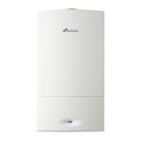
Adjusting the telescopic flue length:
Fig. 29 Standard telescopic flue
Extend tube (1) by withdrawing from tube (2) to achieve the flue length
required, between 350 - 570mm.
Secure with the screws provided and seal joint with the aluminium tape
supplied.
4.5.2 REDUCING THE TELESCOPIC FLUE LENGTH:
The flue terminal MUST be fitted with the 'TOP' label uppermost to allow
the correct fit and use of the plume management system.
Fig. 30 Reducing the standard terminal
▶ Remove securing screws (3) to detach the terminal assembly from
the turret.
▶ Slide terminal section (2) from the terminal assembly and discard.
▶ To use terminal (1) without cutting remove the location lug (4) on the
inner flue tube (5) and remove any burrs.
To reduce the flue length further:
Fig. 31 Further reduction
▶ Mark the length required for the terminal as shown (min. 130mm)
and cut square, taking care not to damage the tubes.
▶ Remove any burrs and chamfer the outer edge of the tubes to assist
ease of connection and prevent seal damage.
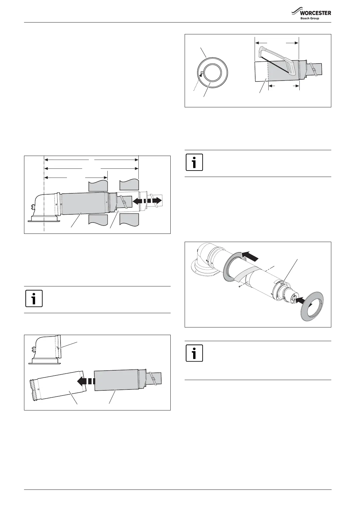
4.5.3 INSTALLING THE TELESCOPIC FLUE:
Refer to figure 32.
1. Set the flue length to the distance required, secure with screws
provided.
2. Seal the joint with the aluminium tape provided.
3. Slide the inner wall seal onto the terminal.
4. If fitting from inside the building; slide the outer wall seal onto the
terminal.
Fig. 32 Telescopic flue
Ensure that the “TOP” label is facing up before securing
the flue section to the turret.
6720643895-30.1Wo
570 mm
350 mm
L
2
1
The aluminium tape is not required when reducing the
terminal.
The turret securing screws are found in the boiler
literature pack, not in flue kit.
Do not remove the 3 flue retaining screws (1) from the
flue connector.
Secure the flue turret at the unused fixing points (2).
4
5
6
1
130 mm
265 mm
MIN
6720643895-32.2Wo
3.
4.
1.
1.
2.
TOP
6720644842-08.1Wo
 Loading...