INSTALLATION
6 720 648 726 (2011/07)
39
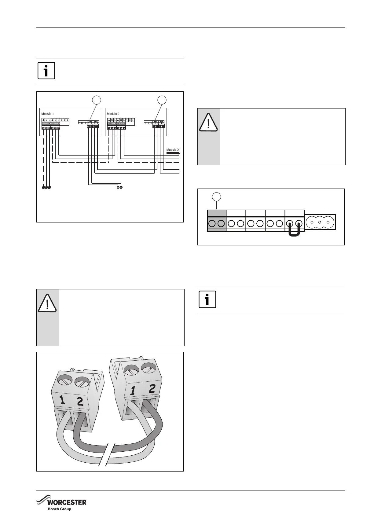
B Connect the 230 V AC mains cable of the first module
to the next module.
Fig. 65 Connecting several modules
B Connect the free connector of the EMS bus
connecting cable to the first module (Æ fig. 64, [2]).
B If more modules are used, the EMS bus connection for
the second module may be branched off from the first
module using the cable enclosed with the module
(Æ fig. 65 and 66).
Fig. 66 EMS bus polarity
INSTALLING AND CONNECTING FUNCTION MODULES
OUTSIDE THE BOILER
B Install the module on the wall.
B Make a sufficiently long EMS bus connection cable,
using a 2-core cable of 0.4 - 0.75 mm² and the
connector enclosed with the module (Æ fig. 66).
Important: Use the connector of the same colour as
the connections on the module.
B Connect the EMS bus connection cable to the orange
connection of the terminal strip [1].
Fig. 67 Terminal strip - Room controller RC and EMS bus
(connection colour orange)
B Connect the other end of the EMS bus connection
cable to the first module (Æ fig. 65).
B If more modules are used, the EMS bus connection for
the second module may be branched off from the first
module using the cable enclosed with the module.
B Connect the EMS bus connection lead of the first
module to the next module (Æ fig. 65).
B Make a sufficiently long 230 V AC mains cable, using
a 3-core cable of at least 0.75 mm² with an earthing
wire, the connector enclosed with the module and a
230 V AC earthed plug.
B Connect the 230 V AC mains cable to the module
(Æ fig. 65). If more modules are used, the 230 V AC
supply to the next module can be branched off from
the previous module using the connector enclosed
with the module and a 3-core 0.75-mm² current cable
with an earthing wire.
B Connect the 230 V AC supply cable of the previous
module to the next module (Æ fig. 65).
The module may have the letters RC or EMS
above the connection [1].
NOTE:
Pay attention to the polarity when using an
EMS bus connection cable..
B Connect the wire from terminal 1 to ter-
minal 1 and from terminal 2 to terminal 2
(Æ fig. 65 and 66).
11
6 720 648 726-065.1TD
To the 230 V AC mains plug
in the earthed socket or a
free connector in the boiler.
To a free connector in the
boiler or the terminal strip.
Note: This connection is not
reverse-proof.
6 720 648 726-066.1TD
NOTE:
Pay attention to the polarity when using an
EMS bus connection cable.
B Connect the wire from terminal 1 to ter-
minal 1 and from terminal 2 to terminal 2
(Æ fig. 65 and 66).
The module may have the letters RC or EMS
above the connection (Æ fig. 65, [1]).
RC
6 720 648 726-067.1TD
1
 Loading...


