Installation
6720813171 (2015/04) 31
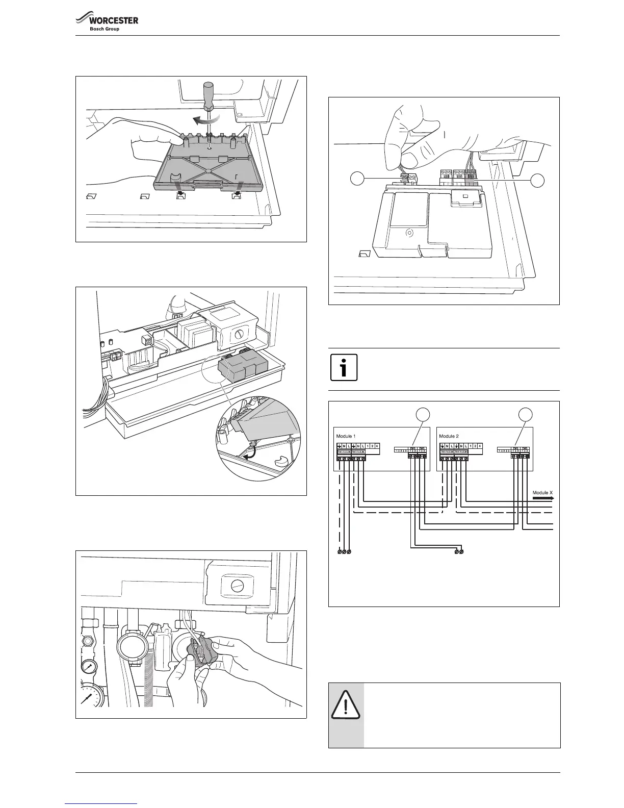
▶ Install the wall bracket (accessory with function module) in the
relevant slots in the draw.
Fig. 61 Installing the wall bracket
▶ Click the function module(s) into place in the wall bracket.
▶ Remove the draw.
Fig. 62 Clicking the function module into place in the wall bracket
▶ Remove the covers of both free connectors on the function module
connection cables.
▶ Slide the draw back into the boiler.
Fig. 63 Removing the covers
▶ Connect the free 230 VAC mains cable ( fig. 63) to the module
[1]. If more modules are used, the 230 VAC supply for the second
module can be taken from the first module using the cable enclosed
with the module.
Fig. 64 Interconnecting modules
▶ Connect the 230 VAC mains cable of the first module to the next
module.
Fig. 65 Connecting several modules
▶ Connect the free connector of the EMS bus connecting cable to the
first module ( fig. 64, [2]).
▶ If more modules are used, the EMS bus connection for the second
module may be branched off from the first module using the cable
enclosed with the module ( fig. 65 and 66).
The module may have the letters RC or EMS above the
connection [1].
NOTICE:
Pay attention to the polarity when using an EMS bus
connection cable.
▶ Connect the wire from terminal 1 to terminal 1 and
from terminal 2 to terminal 2 ( fig. 65 and 66).
To the 230 VAC mains plug in
the earthed socket or a free
connector in the boiler.
To a free connector in the boiler or
the terminal strip. Note: This
connection is not reverse-proof.
 Loading...


