Installation
37
Greenstar 8000 Style – 6720883864 (2019/02)
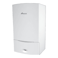
▶ For splash water protection (IP): cut the strain relief to match the
diameter of the cable.
Fig. 52 Adapting the strain relief to the cable diameter
▶ Guide the cable through the strain relief.
▶ Connect the cable to the terminal strip for external accessories.
▶ Secure the cable on the strain relief.
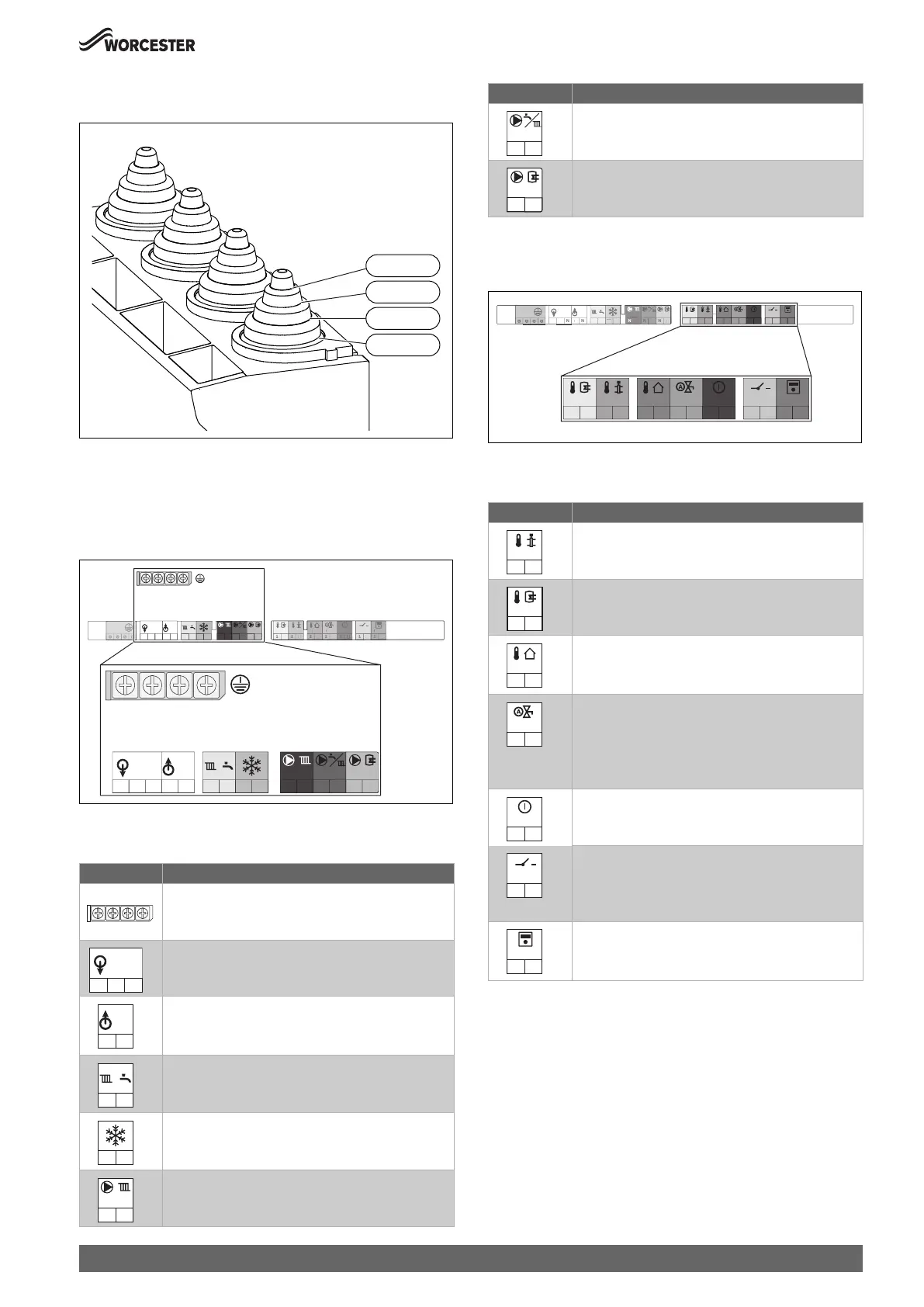
Power supply (power cables) terminal strip
Fig. 53 Power supply (power cables) terminal strip
Power supply (power cables) connections
Table 13 Power supply (power cables) terminal strip for external
accessories
Low voltage (signal cables) terminal strip
Fig. 54 Low voltage (signal cables) terminal strip
Low voltage (signal cables) connections
Table 14 Low voltage (signal cables) terminal strip for external
accessories
Symbol Function
Protective earth bar
▶ Connect the protective earth for power supply.
Power supply (power cable)
Pre-wired cable (Live and Neutral)
230V mains output to external controls/wiring centre
▶ If required: connect power supply for external
controls.
Switch live (Live Return) to appliance
• k CH demand input
• j DHW demand input (pre-heat time control)
External frost thermostat
• FS output (frost thermostat supply)
• FR input (frost thermostat return)
Without function
0010019570-001
5-7Ø
Ø 8-9
Ø 10-12
13-14Ø
0010023703-001
PE
PC0
N
L
PW2
N
L
FS
FR
LR
LR
PW1
N
L
N
IN
230V
OUT
230V
LL
N
TW1
1
2
T1
1
2
T0
1
2
LF0
1
2
I3
1
2
I1
1
2
BUS
1
2
TW
T
T
F
2
I
2
I
PC0
N
L
PW2
N
L
FS
FR
LR
LR
PW1
N
L
N
IN
230V
OUT
230V
LL
N
N
IN
230V
L
OUT
230V
L
N
LR
LR
FS
FR
PC0
N
L
Without function
Without function
Symbol Function
Without function
Without function
Outdoor weather compensation sensor (used when
accessory outdoor sensor is connected)
▶ Connect the outside temperature sensor.
Auto filling link contact.
▶ Connect the auto filling link cable.
▶ Switch on the automatic filling facility in the service
menu under Settings > Special function and
program it according to the heating system.
Without function
Mechanical control accessory and low voltage external
room thermostat contact.
▶ Remove link and connect the on/off temperature
controller.
External control system with EMS bus control,
Worcester intelligent wall mounted controls, Boiler IQ.
▶ Connect 2 core cable.
Symbol Function
PW2
N
L
PW1
N
L
0010023776-001
TW1
1
2
T1
1
2
T0
1
2
LF0
1
2
I3
1
2
I1
1
2
BUS
1
2
PE
PC0
N
L
PW2
N
L
FS
FR
LR
LR
PW1
N
L
N
IN
230V
OUT
230V
LL
N
TW1
1
2
T1
1
2
T0
1
2
LF0
1
2
I3
1
2
I1
1
2
BUS
1
2
P
PW
L
F
F
L
W
230
UT
230V
T0
1
2
TW1
1
2
T1
1
2
LF0
1
2
I3
1
2
I1
1
2
BUS
1
2