Inspection and maintenance
Greenstar 8000 Style – 6720883864 (2019/02)
58
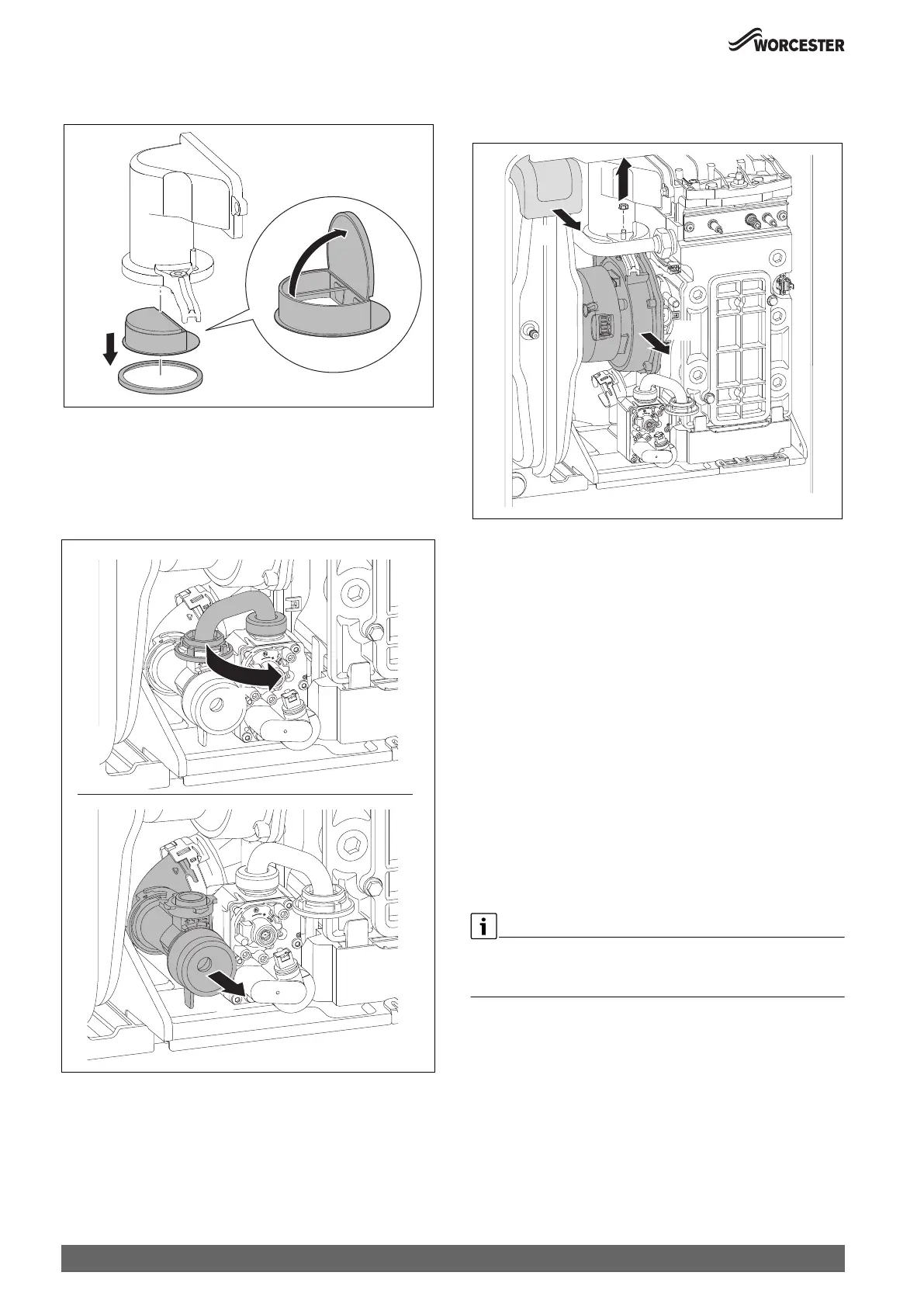
1. Remove the non-return valve.
2. Check the non-return valve for contamination and cracks.
Fig. 79 Non-return valve in the air-gas manifold
▶ Install the non-return valve.
▶ Install the air-gas manifold.
8.9.3 Fan removal
1. Undo connection of venturi.
2. Remove venturi and move pipe to the far right.
Fig. 80 Venturi removal
3. Remove expansion foam (pull towards you).
4. Undo fan connection and remove screw and seal.
5. Remove fan.
Fig. 81 Fan removal
8.9.4 Cleaning the heat exchanger
Access to the heat exchanger
The following items will have to be removed to gain access to the heat
exchanger for cleaning:
▶ Remove the combustion casing.
▶ Lower the control panel into the service position.
▶ Disconnect electrical wires to the fan, ignition transformer, spark
electrodes, flue overheat thermostat, main heat exchanger
temperature sensor and flow pipe temperature sensor.
▶ Flueway
▶ Fan assembly
▶ Ignition transformer
▶ Spark electrode assembly
▶ Burner housing, burner and gasket
Cleaning the heat exchanger
▶ Remove the siphon and place a suitable container under the outlet to
catch the water and debris.
▶ Protect the controller from water ingress.
The heat exchanger does not have to be removed in order to clean.
The heat exchanger is shown removed from the appliance to illustrate
cleaning more clearly.
1.
2.
0010007068-001
0010023759-001
2.
1.
0010023760-001
4.
5.
3.