Installation
Greenstar 8000 Style – 6720883864 (2019/02)
38
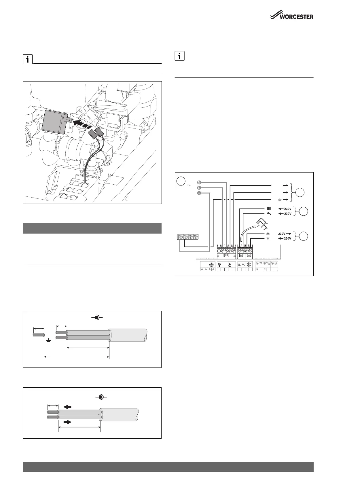
Connecting the automatic filling (accessory)
▶ Flip down the control unit( Fig. 51).
▶ Plug cables to solenoid valve.
Cables are not polarity sensitive.
Fig. 55 Connecting the automatic filling facility
5.5.2 Cable preparations
NOTICE:
Damage to control unit!
Small pieces of wire can cause shorts and damage to electronics.
▶ When stripping wires always ensure copper strands do not fall into
the control box.
Mains voltage (power cables), example figure 56
▶ Ensure the conductors (C) can reach the appropriate terminal
connection and that the protective (earth) conductor is longer than
the other wires.
– Power cables connected to the appliance my have different
conductor lengths depending on the termination point.
Fig. 56 Mains voltage (power cables) preparation
Low voltage (signal cables), example figure 57
Fig. 57 Low voltage (signal cables) preparation
5.5.3 External controls - domestic installations
Appliance external control connections example
External 230V single channel timers:
▶ Leave DHW pre-wired link in place.
▶ The electrical power supply to the external equipment [2] is supplied
from 230V OUT - L (Live), N (Neutral) and \ (earth) terminals.
▶ The Switch Live from the external equipment [3]:
– Heating/zone controls connects to (LR terminal, remove CH
pre-wired link only.
– Control for appliance Pre-heat function, optional.
Hot water time controller connects to * LR terminal, remove
pre-wired link (only use when a Worcester controller has been
fitted that does not have DHW pre-heat time control available or
no Worcester controller fitted).
▶ External frost thermostat connections [4]:
– The Live supply is terminal FS
– The Switch Live is terminal FR
Fig. 58 External controls connections example
[1] 230V mains supply to the appliance.
[2] 230V supply from the appliance to the external controls.
[3] CH & DHW Switch Live (Demand) from the external controls.
[4] External frost protection Live supply and Switch Live (Demand).
0010020494-002
0010023711-001
> C
C
6-8mm
6-8mm
N
L
230V
0010012956-001
26-30mm
6-8mm
0-30V
0010022764-001
FS
FR
PE
P
PW
FS
FR
LR
LR
W
N
N
IN
230V
OUT
230V
LL
N
LR
LR
3
N
L
2
4
230V OUT
1
230V AC