6 720 611 137 GB (03.02)
30
Converting the appliance to different gas types
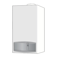
B Turn the function control until the display shows 2.
(= max. rated heat output).
The display and the button will flash.
Fig. 43
B Measure the CO
2
level.
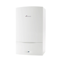
B Prise off the seal on the gas flow restrictor.
B Adjust the gas flow restrictor (63) to obtain the CO
2
level given in Table 14. Refer to fig. 44.
Fig. 44
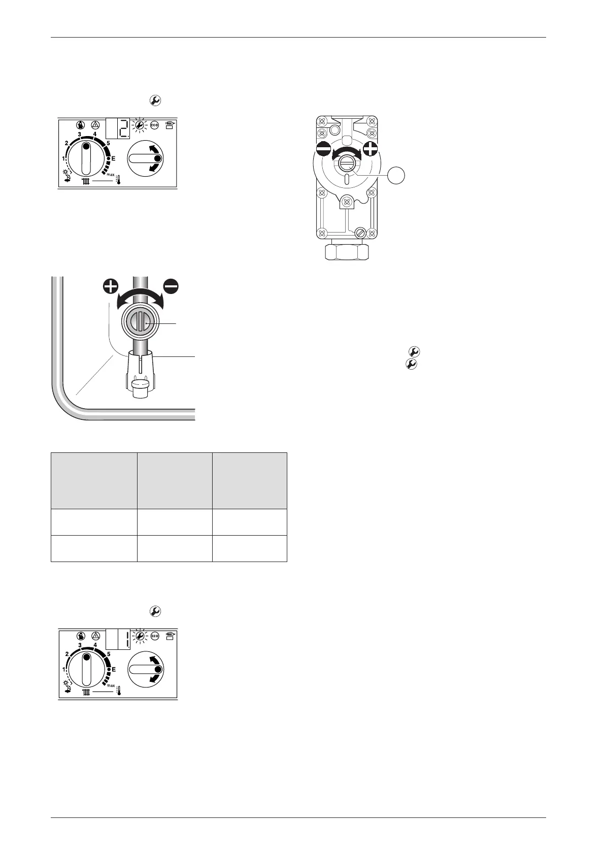
B Turn the function control anti-clockwise until the dis-
play shows 1. (= min. rated heat output).
The display and the button will flash.
Fig. 45
B Measure the CO
2
level.
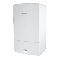
B Remove the seal from the gas valve adjusting
screw (64) and adjust the CO
2
level to the figure
given in Table 14 for min. rated heat output.
Fig. 46
B Recheck the levels at min. and max. rated heat output
and re-adjust if necessary.
B Turn the function control anti-clockwise as far as the
stop so that the display shows 0.
(= Normal operating mode).
The display and the button will flash.
B Press and hold the button until the display
shows [ ].
B Reset the temperature control and the function con-
trol to their original positions.
The display will revert to the boiler flow temperature.
B Remove testing probe from the flue gas testing
point (234) and refit sealing plug.
B Re-seal gas valve adjusting screw and gas flow
restrictor.
B Replace outer case and secure.
B Set room thermostat and thermostatic radiator valves
to the desired temperature.
Gas Type
CO
2
reading
at max.
rated heat
output
CO
2
reading
at min.
rated heat
output
Natural gas type
(G20)
9.2 % 8.8 %
LPG (G31)
(propane)
10.8 % 10.5 %
Table 14
6 720 611 137-20.1O
63
6 720 610 332-64.1R
6 720 611 137-21.1O
64
3928-74.1R