6 720 611 137 GB (03.02)
Maintenance
35
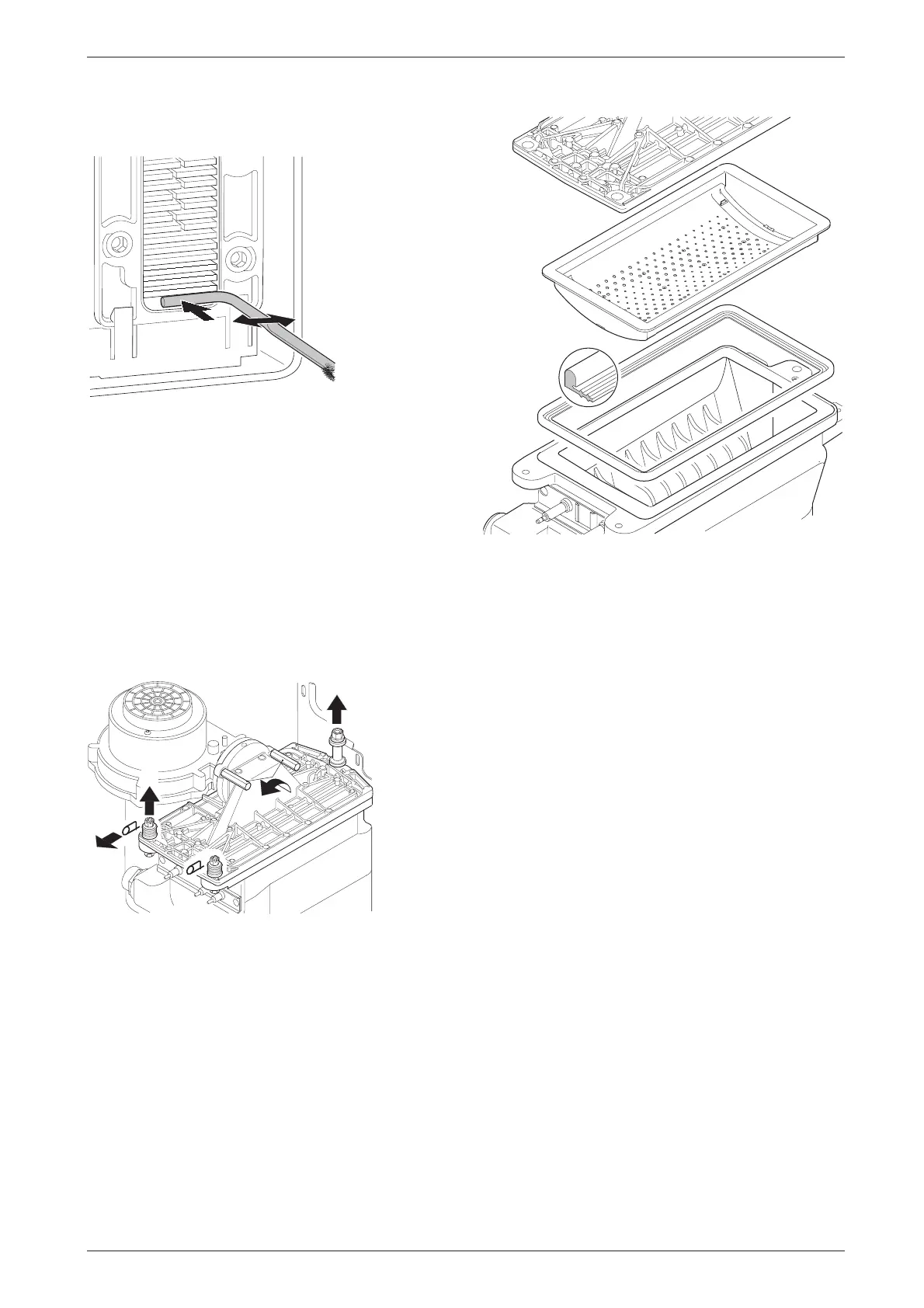
B Clean out the condensate collector and trap connec-
tion (with other end of brush).
Fig. 52
B Refit the clean-out cover using a new seal and
tighten screws to torque of approx. 5 Nm.
Burner
B Check that the gas cock is turned off and the master
switch is in the OFF position.
B Remove the clips (1) and unscrew the two bolts (2).
Refer to fig. 53.
B Unscrew and remove the two hexagon screws secur-
ing the fan (3).
B Slacken fully the rear securing bolt (4).
B Remove the burner coverplate.
Fig. 53
B Remove the burner skin and clean components. Do
not use a wire brush. Refer to fig. 54.
Fig. 54
B Re-assemble burner in reverse order using a new
seal.
B Adjust gas/air ratio. Refer to section 7.2.
Condensation trap
In order to prevent spillage of condensate, the conden-
sation trap should be completely removed, (see
page 34, fig. 49).
B Unscrew condensation trap and check connection
to heat exchanger is clear.
B Remove condensation trap cover and clean.
B Fill condensation trap with approx. 1/4 l of water and
refit.
Electrode assembly
B Switch off the master switch.
B Pull off the leads from the electrodes. Refer to fig. 2.
B Unscrew the two fixing screws and carefully remove
the electrode assembly. Refer to fig. 48.
B Clean the electrodes with a non-metallic brush. (The
spark gap should be 4,5 mm ± 0,5 mm.)
B Replace and re-connect the assembly taking care
not to mislay the inspection window.
6 720 610 332-75.2R
1.
2.
4.
7 181 465 330-04.1R
3.