PRE-INSTALLATION
6 720 804 532 (2012/09) 11
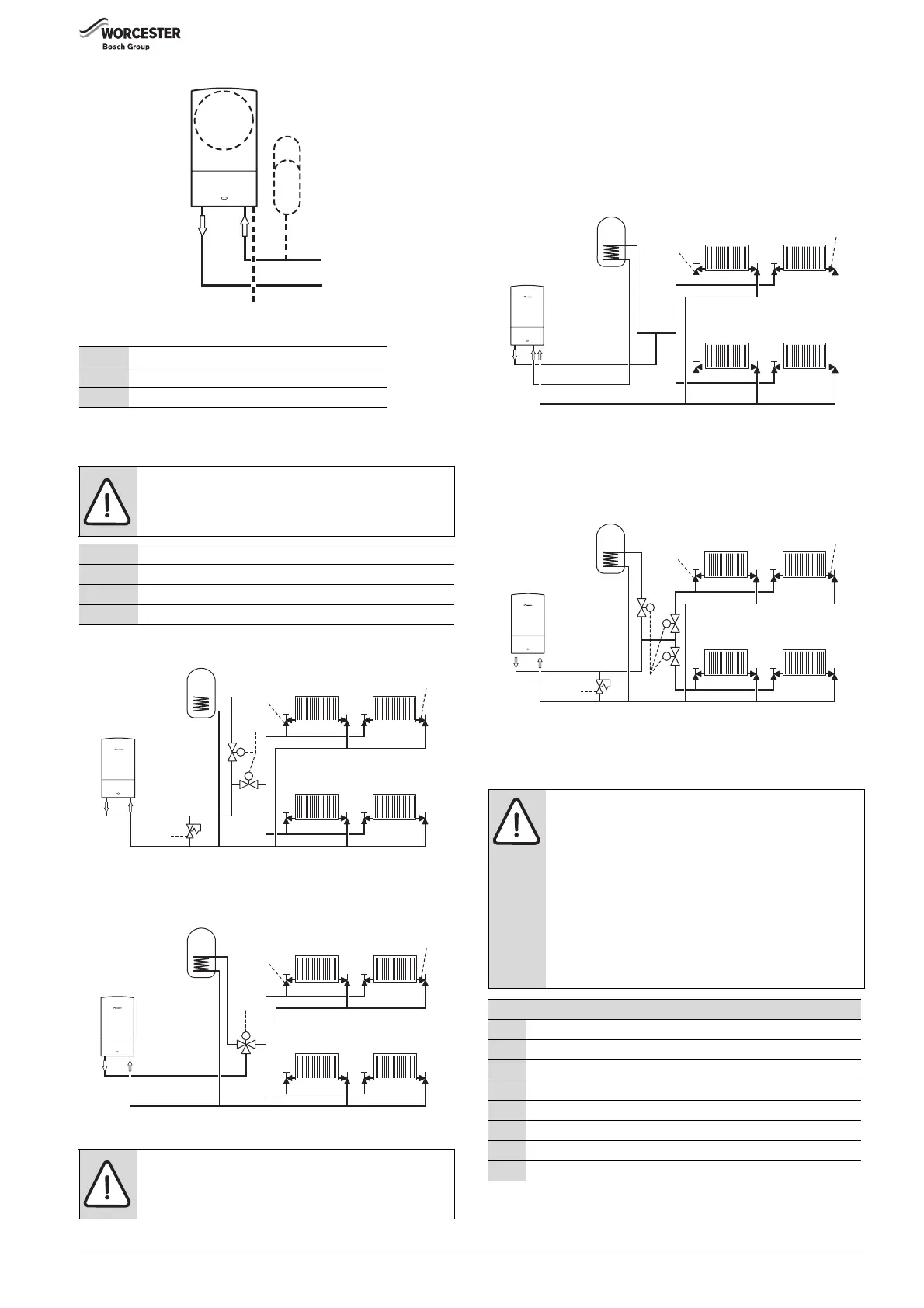
Fig. 5 Additional expansion vessel
EXISTING BUILDS: S AND Y PLAN SYSTEMS:
S PLAN LAYOUT
Fig. 6 Existing build - S Plan
Y PLAN LAYOUT WITH EXTERNAL DIVERTER VALVE
Fig. 7 Existing build - Y Plan external diverter valve
OPTIONAL DIVERTER VALVE
This boiler is designed to operate on a sealed system only. The boiler will
require a second return pipe from the water cylinder to the wall
mounting frame and terminate in 15mm copper pipe.
EXISTING BUILD - SYSTEM LAYOUT WITH OPTIONAL INTERNAL
DIVERTER VALVE (NOT SUPPLIED WITH BOILER)
Fig. 8 Existing build - Internal diverter valve
NEW BUILD - TWO ZONED HEATING SYSTEM
The latest Part L1a regulation for new installations require separate zone
controls for the central heating.
Fig. 9 New build - System layout
3.4 CONDENSATE PIPE WORK
1 Appliance expansion vessel - CH
2 Extra expansion vessel - CH return
3 Pressure relief discharge
Table 7 Key to fig. 5
NOTICE: The boiler is fitted with its own internal bypass.
1 Diverter/Zone valve
2 Radiator valve (flow)
3 Lock shield valve (return)
4Bypass
NOTICE:
▶ A drain cock should be fitted at the lowest point of the
heating circuit and beneath the appliance.
NOTICE:
▶ Where a new or replacement boiler is being installed,
access to an internal “gravity discharge” point should
be one of the factors considered in determining boiler
location.
▶ The condensate pipe must be nominally
22mm Ø plastic pipe.
▶ The condensate pipe work must fall at least 52mm per
metre towards the outlet and should take the shortest
practicable route.
▶ Ensure there are no blockages in the pipe run.
Key to condensate illustrations
1 Condensate discharge from boiler
2 Soil and vent stack
3 Minimum 450mm and up to three storeys
4 Visible air break at plug hole
5 Sink or basin with integrated overflow
6 75mm sink waste trap
7 Condensate pump
* Condensate trap of 75mm already incorporated into the boiler
Boiler flow
Cylinder return
Heating return
3
2
6720644743-07.1Wo
6720644743-42.1Wo
3
2
1
4
M
MM
 Loading...