SERVICE AND SPARES
6 720 804 532 (2012/09) 41
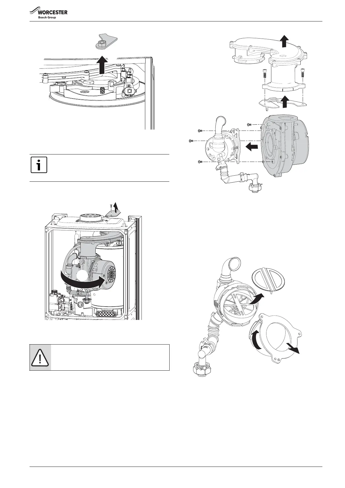
Fig. 95
▶ Undo the securing nut at the top of the heat exchanger and remove the
retaining plate assembly (1).
▶ Rotate fan and air/gas manifold assembly (1.) around the top of the
heat exchanger until the lug on the air/gas manifold is visible.
Fig. 96 Rotate the air/gas manifold assembly
▶ Lift up assembly and remove from boiler.
6.8.8 FAN
▶ Remove the air/gas manifold from the boiler as described in the
previous section.
1.Remove two screws retaining the fan to the air/gas manifold.
2.Remove the air/gas manifold.
3.Remove the screw holding the retaining plate.
4.Remove the retaining plate.
5.Remove three screws and the mixing chamber.
Re-assemble with new fan ensuring seals are correctly fitted.
Fig. 97 Dismantling the air/gas manifold assembly
FLAP VALVE ASSEMBLY
1. Twist the mounting flange clockwise to release.
2. Pull mounting flange off the flap valve assembly.
3. Pull rubber flap off flap valve assembly.
▶ To replace the flap valve:
– Press the two lugs on the back of the flap into the two slots in the
flap valve assembly.
Fig. 98 Flap valve assembly
6.8.9 ELECTRODE ASSEMBLY AND BURNER
▶ Refer to figure 99 and disconnect spark electrodes and flame sensor
connection.
▶ Remove clamping plate.
1. Remove spark/flame electrode assembly from heat exchanger.
2. Remove the seal from the top of the heat exchanger.
3. Remove the burner.
▶ Replace new burner in correct position.
Disconnect spark electrodes and flame sensor
connection.
This will prevent damage to the electrodes and sensor
when the air/gas manifold is rotated.
NOTICE: After re-assembly, check the CO/CO
2
levels as
described in section 6.6 Setting the air/gas ratio.
4.
1.
2.
1.
3.
6.
5.
5.
5.
6720643895-81.1Wo
 Loading...