INSTALLATION
6 720 804 532 (2012/09) 21
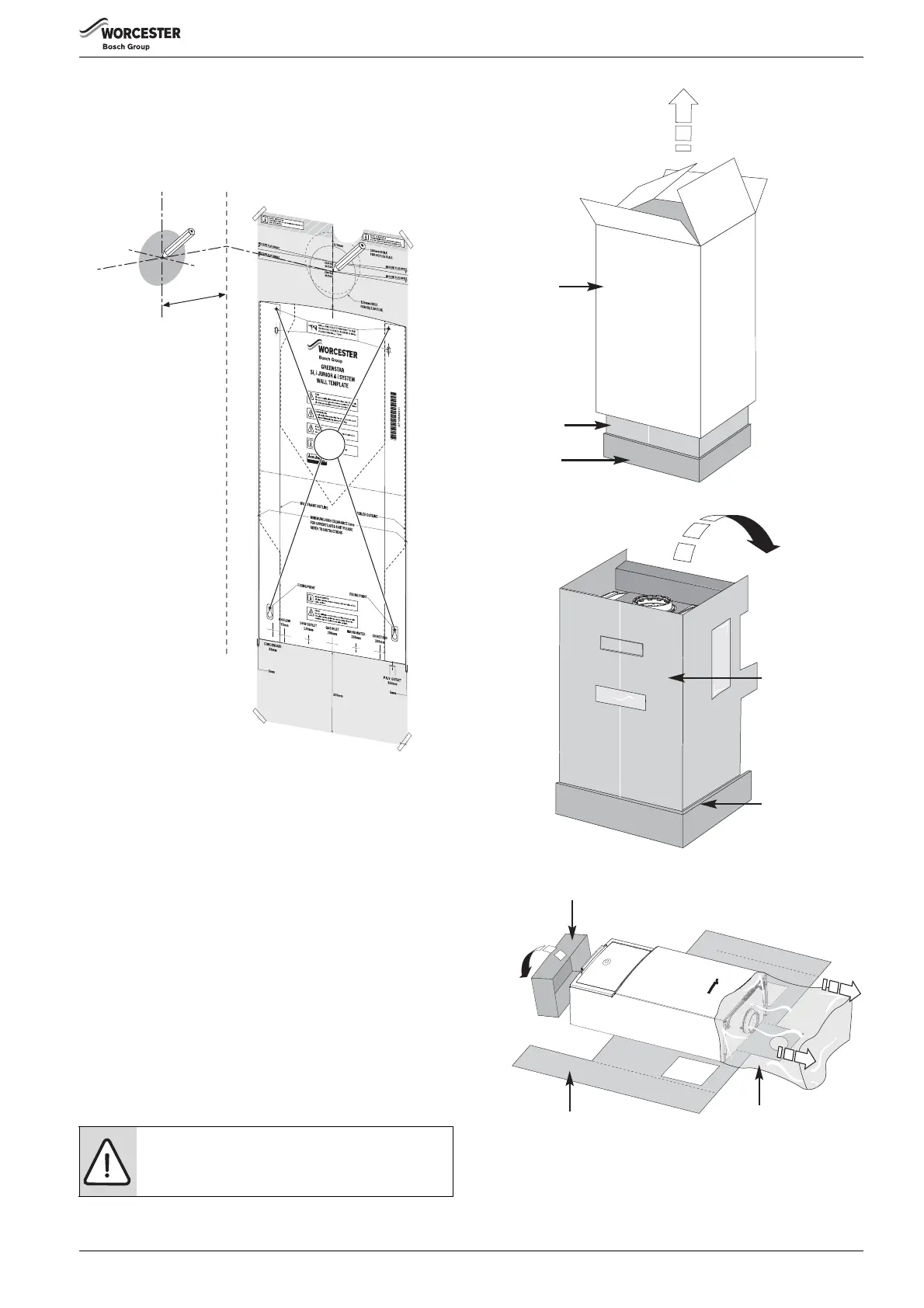
SIDE OUTLET:
4. Mark from the centre line of the wall template to the wall which the flue
will pass through (4).
▶ Allow for a rise of 52mm per metre length of flue, to give a 3° angle.
▶ Clear any debris from the site.
Fig. 25 Marking the flue position
4.3 UNPACKING THE APPLIANCE
1.Outer carton
2.Inner sleeve (unwrap from front)
3.Packing base
4.Protective wrapping
5.Appliance outer case
▶ Remove outer carton (1) and place safely away from the working area.
▶ With the outer packaging removed and the inner sleeve (2) still in
place gently lay the boiler on its back.
▶ The boiler will lie at an angle to the floor to allow the boiler outer casing
(5) to be removed.
▶ The inner sleeve (2) opens as shown in figure 28.
▶ Remove the protective wrapping (4).
1.Undo but do not remove the two screws at the bottom of the boiler
2.Undo the two screws at the top (see fig. 29).
3.Remove the outer case (5).
▶ Remove any packaging within the boiler and the packaging base (3).
Fig. 26 Remove outer carton
Fig. 27 Lay boiler down
Fig. 28 Remove packaging
CAUTION: Hanging the boiler
▶ Remove the plastic strip fitted to pipes before
hanging the boiler.
6720643895-17.2Wo
4.
1.
3.
189 mm
2.
1
2
3
6720643895-18.1Wo
 Loading...