PRE-INSTALLATION
6 720 804 532 (2012/09)14
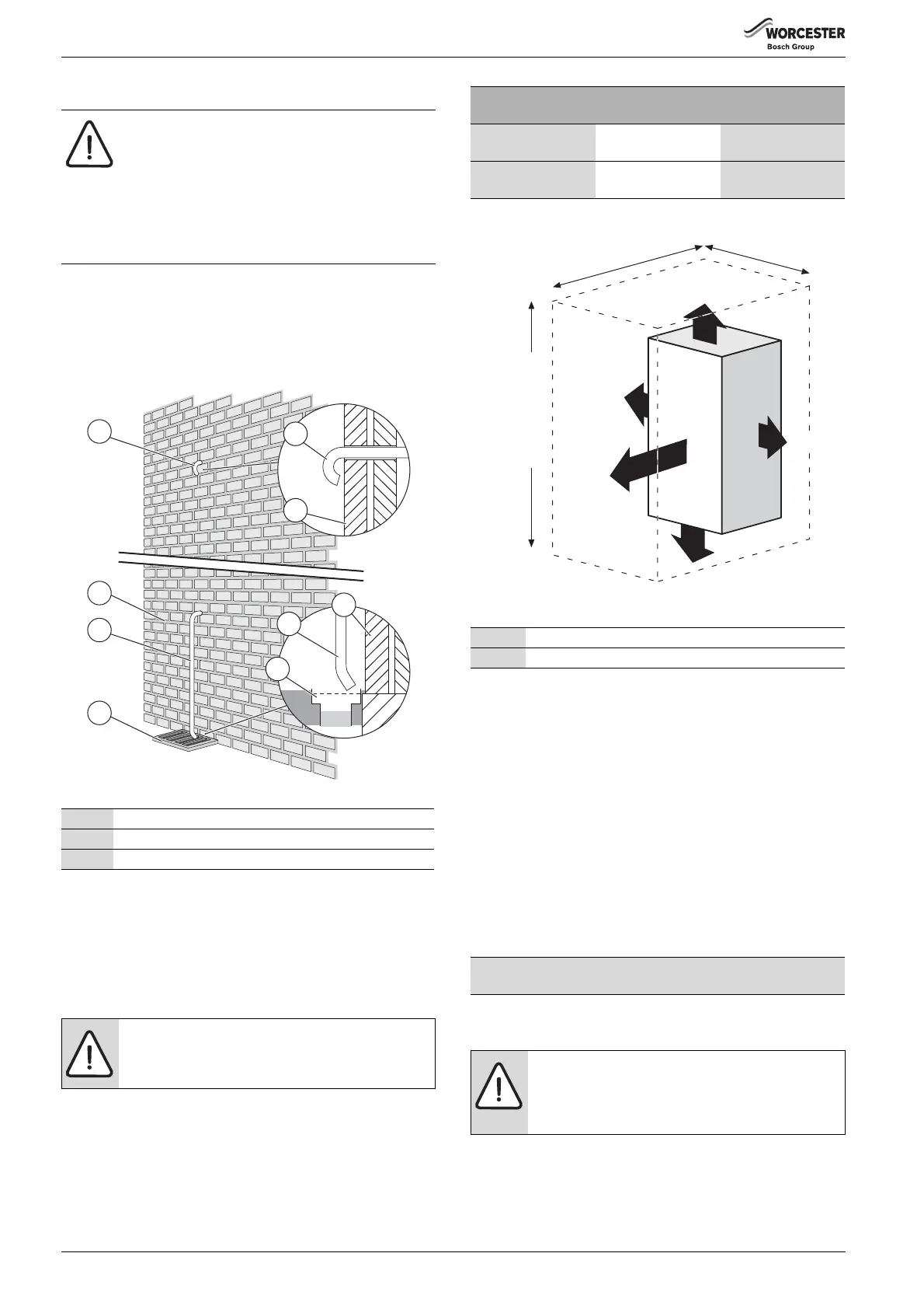
3.5 PRESSURE RELIEF PIPE WORK
• The pressure relief drain pipe (1) from the boiler should be at least
15mm diameter copper pipe and run downwards, away from any
electrical equipment or other hazard, preferably to an external drain
or soak away.
• Pipe (1) should be finished with a partial bend, near the outlet to face
the external wall (as shown) to help prevent freezing.
Fig. 17 Pressure relief pipe work
3.6 BOILER LOCATION AND CLEARANCES
3.6.1 INSTALLATION
This boiler is only suitable for installing internally within a property at a
suitable location onto a fixed, rigid surface at least the same size as the
boiler and capable of supporting the boiler weight.
3.6.2 SERVICING CLEARANCES -
VENTILATED COMPARTMENT
Figure 18 shows the minimum space required to install and service the
boiler in a ventilated compartment.
• If a boiler is installed in a compartment with clearances less than
shown in the tables 11, 12, or 13 ventilation is required. Refer to
table 9 for ventilation requirements.
Fig. 18 Ventilated compartment
3.6.3 COMPARTMENTS:
Follow the requirements of BS6798 and BS5440 Part 2 and note:
• Minimum clearances must be maintained.
• An access door is required to install, service and maintain the boiler
and any ancillary equipment.
• If the boiler is installed in an unventilated airing/storage cupboard,
there is no requirement to make a partition between the boiler and the
storage space as long as the minimum clearances around the boiler
are maintained.
• Ideally, storage should be below the boiler, where the boiler is
mounted in the upper part of the cupboard, whilst maintaining the
clearances given in tables 11, 12, or 13.
3.6.4 BOILER CLEARANCES- UNVENTILATED COMPARTMENTS
3.6.5 INSTALLATION CLEARANCES - UNVENTILATED
COMPARTMENTS
NOTICE:
▶ The pressure relief valve is a safety device for the
boiler and if activated may discharge boiling water or
steam through the relief valve drain pipe.
▶ Care should be taken when siting the outlet pipe so
that it does not cause an obstruction or discharge
above a window, entrance or other public access
where it could cause a hazard.
2Outside wall
1,3 Drain pipe
4External drain
Table 8 Key to fig 7
NOTICE:
No surface protection is required against heat transfer
from the boiler
1
2
3
4
2
3
4
1
2
6720646608-123.1Wo
Vent position
To room or internal
space
Direct to outside
High level Minimum free area
122 cm
2
Minimum free area 61
cm
2
Low level Minimum free area
122 cm
2
Minimum free area 61
cm
2
Table 9 Compartment ventilation
* Minimum clearance to removable door
** Minimum clearance required for servicing
Table 10 Minimum clearances
The tables below show the options for the minimum space required to
install and service the boiler inside an unventilated compartment.
CAUTION: CLEARANCES
▶ Top and bottom clearances must not be reduced
below the values shown in table 11 as they are the
minimum clearances required for servicing.
6720643895-121.2Wo
+ 30 mm
above elbow
930 mm 410 mm
20 mm*
600 mm**
5 mm
Using 100 mm
ue kit
1080 mm
Using 125 mm
ue kit
1100 mm
200 mm
5 mm
 Loading...