SERVICE AND SPARES
6 720 804 532 (2012/09)42
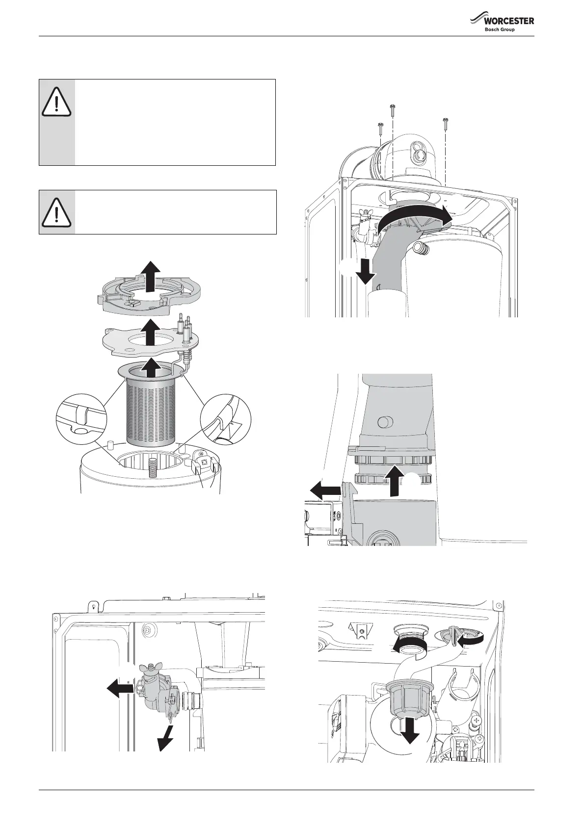
▶ Ensure that burner tabs, as shown in figure 99, fit correctly their
respective locations.
▶ Ensure that the seal is fitted.
▶ Replace the clamping plate.
Fig. 99 Electrode assembly and burner
6.8.10 HEAT EXCHANGER
▶ Isolate flow and return valves then drain the boiler.
▶ Remove syphon.
1. Refer to figure 100 and remove the clip from plastic elbow on the flow
pipe.
2.Pull flow pipe away from heat exchanger.
Fig. 100 Flow pipe removal
1. Refer to figure 101 and remove the three screws securing the turret
to the top of the boiler.
2. Turn the upper exhaust connector clockwise to release from the hook.
3. Pull the upper exhaust connector down.
Fig. 101 Upper exhaust assembly
1. Refer to figure 102 and release the clip.
2. Move the lower exhaust connector up
▶ Remove the complete exhaust assembly.
Fig. 102 Release lower exhaust connection
1. Refer to figure 103 and unscrew the plastic nut.
2. Remove the nut from the bottom of the boiler.
3. Rotate lever to release the return pipe.
Fig. 103
NOTICE: Heat exchanger seal
▶ If the joint between the Air/Gas manifold and heat
exchanger is disturbed sealing gasket must be
replaced.
▶ After re-assembly the combustion must be checked
using the procedure in the section 6.6 “Setting the
Air/Gas ratio”.
CAUTION: Clamping plate
▶ Ensure that the clamping plate is firmly tightened
down on top of the heat exchanger.
 Loading...