6 720 610 597 GB (01.07)
14
Installation
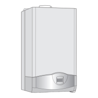
3.5 Wall mounting frame assembly
y Take the wall mounting frame out of the package and
screw together with 6 screws as shown in fig. 7. Use
the outer lugs on the top and bottom horizontal sec-
tions for the appliances that are 512 mm wide.
Fig. 7
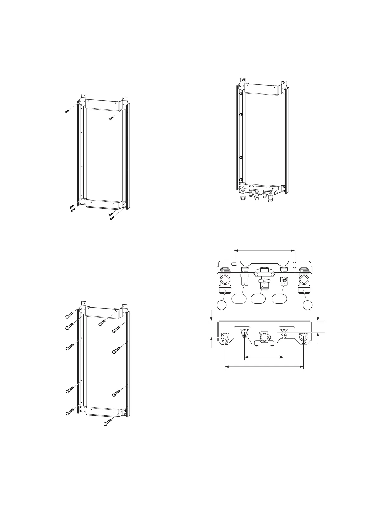
y Hold the wall-mounting frame against the wall ensur-
ing that it is vertical.
y Mark the postion of the flue duct hole if a rear flue is
to be used. Refer to fig. 1 and 15.
y Mark the holes for the wall mounting frame onto the
wall, drill and plug the holes and screw the wall
mounting frame to the wall with the screws provided.
Fig. 8
y Screw the pre-plumbing manifold with two screws to
the wall mounting frame.
Fig. 9
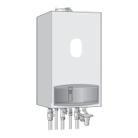
3.6 Pre-piping the system
Fig. 10 Manifold
43 CH flow
47 CH return
112 Gas cock
171 Domestic hot water
172 Cold water relief
y A drain tap should be fitted at the lowest point of the
central heating system.
y WRc filling loop must be fitted.
6 720 610 597-06.1O
6 720 610 597-07.1O
6 720 610 597-08.1O
200
260
6 720 610 576-06.1O
35
120-130
50
4743
172112
171
 Loading...