6 720 610 597 GB (01.07)
36
Maintenance
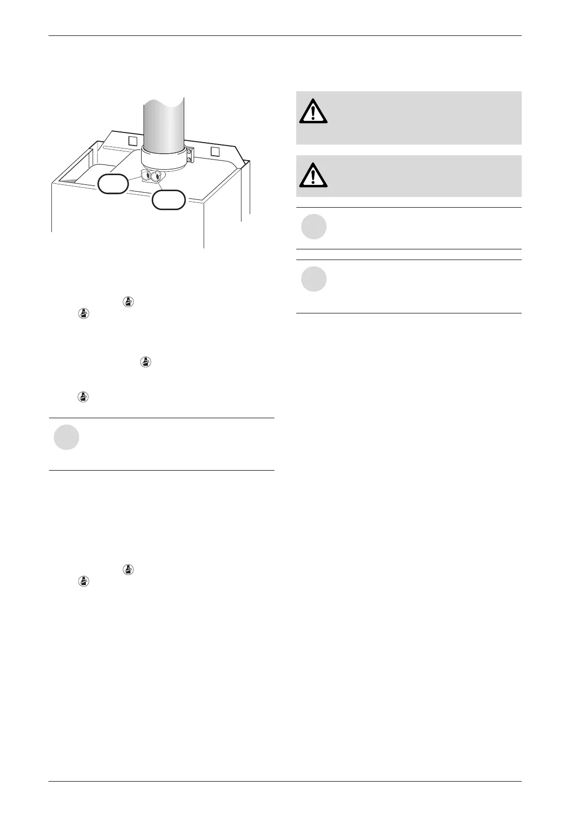
y Insert testing probe about 80 mm into the testing
point and seal testing point.
Fig. 42
y Measure O
2
and CO
2
levels.
y Refit sealing plug.
y Press and hold button until the display shows – –.
The button will stop flashing and the display
shows the CH flow temperature.
8.2.2 Testing CO and CO
2
y Press and hold the button until the display
shows – –.
“Chimney sweep” mode is now active.
The button will light up and the display shows the
CH flow temperature.
y Remove sealing plug from flue gas testing point
(234, Fig. 42).
y Insert testing probe about 135 mm into the testing
point and seal testing point.
y CO- and CO
2
levels.
y Refit sealing plug.
y Press and hold button until the display shows – –.
The button will stop flashing and the display
shows the CH flow temperature.
9 Maintenance
y The User should be recommended to have the appli-
ance serviced regularly by a competent person.
y Use only genuine spare parts
y Refer to the Spare Parts List when ordering spare
parts.
y Always renew seals and O-rings removed during
servicing or repair work.
y Use only the following types of grease:
– Water valve: WRc approved silicon based grease
– Unions: approved sealant.
y To drain the appliance shut the system valves and
open the pressure relief valve.
Replace the text display module or the Heatronic
PCB
If the text display module is replaced, the service func-
tion settings are retained.
y The remaining settings have to be re-entered.
If the Heatronic PCB is replaced:
y Re-enter the service function settings as recorded in
the commissioning record.
i
You have 15 minutes in which to measure
the levels. After that, the appliance switch-
es back from “chimney sweep” mode to
normal mode.
6 720 610 332-65.1R
234
234.1
y Always disconnect the appliance from
the electrical power supply (fuse, circuit
breaker) before carrying out any work on
the electrical systems or components.
y Always turn off the gas cock before car-
rying out any work on components
which carry gas.
i
There is a Service booklet for the Engi-
neer, order no. 7 181 465 347, available
to competent persons.
i
All safety and control systems are moni-
tored by the Bosch Heatronic. In the event
of a component fault, the textdisplay
shows a fault code.
 Loading...