34
USER MANUAL FOR WTS TOWERS
DYNSYS SYSTEM
The lifters that incorporate the DYNSYS system are named as WTS xxx DY:
- WTS 256 DY - WTS 375 DY - WTS 506 DY - WTS 905 DY - WTS 708 DY - WTS 1206 DY
EXPLANATION
DYNSYS system is a solution for the control of the maximum load in lifting systems.
DYNSYS limits the maximum load of the tower avoiding raising a higher load than the specified when the
tower is used as mechanism. For more information about the maximum load, consult the load chart.
In case of raising a load higher than the maximum, DYNSYS detects the increase in load and prevents it
from being raised, allowing only the descent of the load.
DYNSYS system works as a preventive maintenance element. In case the tower has some internal damage
and forces the system to operate in a forced manner, DYNSYS system will limit its use, preventing that the
internal components (cable, pulleys, profiles, etc. ...) may deteriorate further. If this happens, contact the
technical department or your nearest distributor.
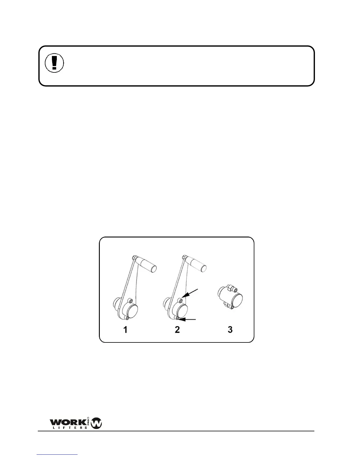
The system allows the disassembly of the crank, thus allowing the blocking of the tower. In this way it is
avoided that personnel outside the installation can manipulate the tower by raising or lowering it. Only
the two Allen screws should be removed.
Figure 103
The system has several elements working in a coordinated manner. On the one hand, the most external
aluminum profile has a special machining to house the safety pin, and the iron carriage has the mechanics
of overload detection and a status marker.
Finally, the original handle of the winch is replaced by a specific one for the DYNSYS system.