ENGINE
WG972-E4, WSM
1-S44
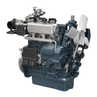
Clearance between Valve Stem and Valve Guide
1. Remove carbon from the valve guide section.
2. Measure the valve stem O.D. with an outside micrometer.
3. Measure the valve guide I.D. with a small hole gauge, and
calculate the clearance.
4. If the clearance exceeds the allowable limit, replace the valves.
If it still exceeds the allowable limit, replace the valve guide.
9Y1211108ENS0070US0
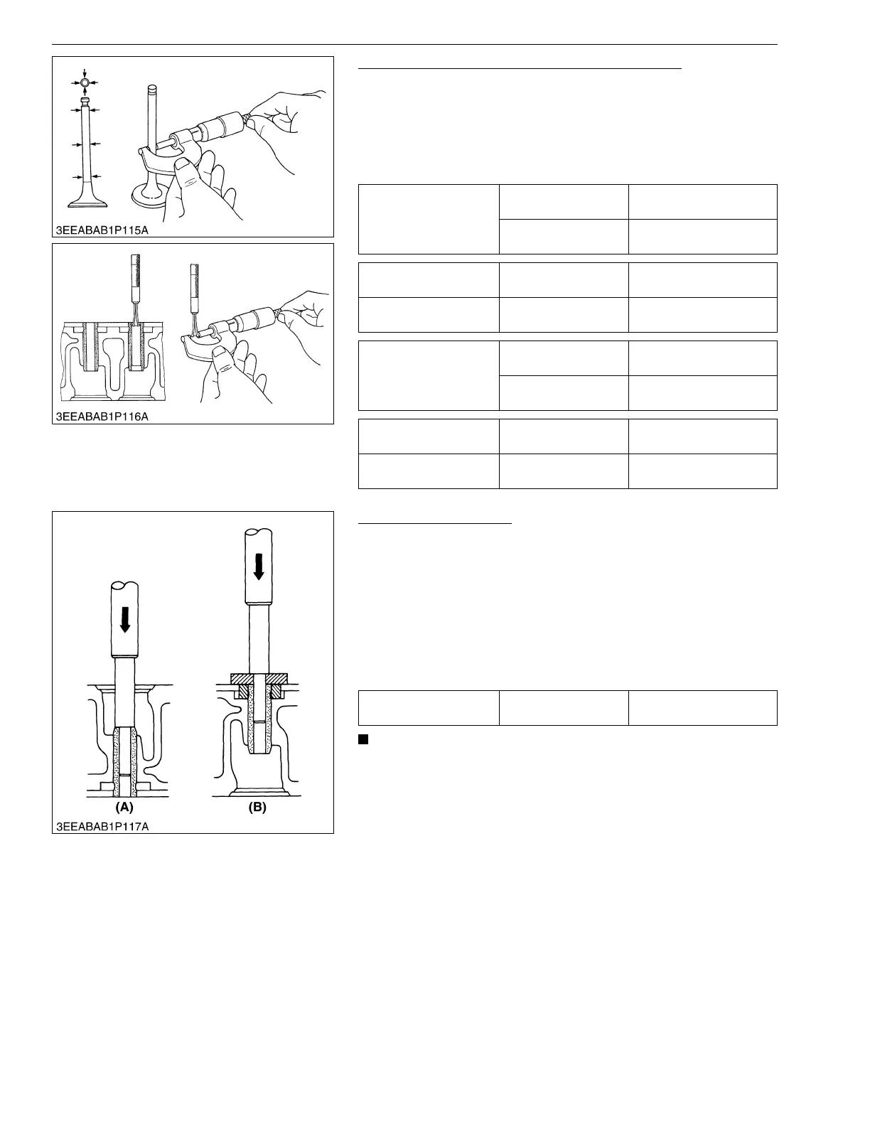
Replacing Valve Guide
(When removing)
1. Press out the used valve guide using a valve guide replacing
tool.
(When installing)
1. Clean a new valve guide and valve guide bore, and apply
engine oil to them.
2. Press in a new valve guide using a valve guide replacing tool.
3. Ream precisely the I.D. of the valve guide to the specified
dimension.
• Do not hit the valve guide with a hammer during
replacement.
9Y1211108ENS0071US0
Clearance between
valve stem and valve
guide (Inlet)
Factory specification
0.030 to 0.057 mm
0.0012 to 0.0022 in.
Allowable limit
0.10 mm
0.0039 in.
Valve stem O.D. (Inlet) Factory specification
5.965 to 5.980 mm
0.2348 to 0.2354 in.
Valve guide I.D. (Inlet) Factory specification
6.010 to 6.025 mm
0.2367 to 0.2372 in.
Clearance between
valve stem and valve
guide (Exhaust)
Factory specification
0.030 to 0.057 mm
0.0012 to 0.0022 in.
Allowable limit
0.10 mm
0.0039 in.
Valve stem O.D.
(Exhaust)
Factory specification
5.968 to 5.980 mm
0.2350 to 0.2354 in.
Valve guide I.D.
(Exhaust)
Factory specification
6.010 to 6.025 mm
0.2367 to 0.2372 in.
Valve guide I.D.(Intake
and exhaust)
Factory specification
6.010 to 6.025 mm
0.2367 to 0.2372 in.
(A) When Removing (B) When Installing