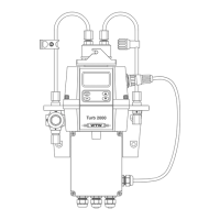
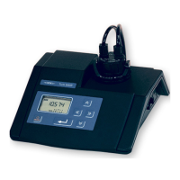
Overview Turb 2000 Series
6 ba75695e03 10/2013
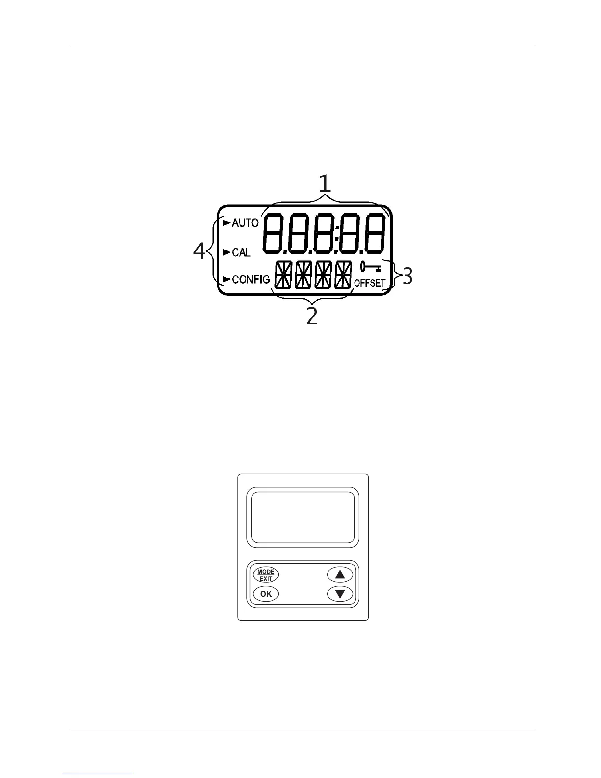
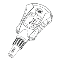
1.3 The display
Figure 1 illustrates all the items that can appear on the display. The upper row of the display (1) is used
for reporting the turbidity levels and to provide user guidance in the customer setting routine. The lower
row of the display (2) is used to communicate error messages and provide user guidance. The display
has two icons (3) that are used to indicate the use of access code and offset mode. In addition, mode
arrows (4) are used to indicate the current instrument operating mode; AUTO (normal operation), CAL
(calibration) and CONFIG (configuration).
Figure 1 – Display used in the instrument.
All items used on the display are shown in this figure
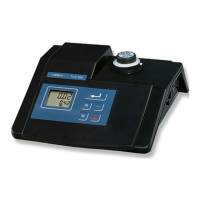
1.4 Keypad
Figure 2 illustrates the touch pad. The touch pad has four buttons: MODE/EXIT, OK, , and . The
MODE/EXIT button is used to cycle between the three operational modes of the instrument: CAL,
CONFIG, and AUTO (Measurement) mode. The OK button enters the option (or mode) that is
highlighted or chosen. The and buttons are used to change settings.
Figure 2: Keypad