Turb 2000 Series Installation and commissioning
ba75695e03 10/2013 11
2.2 Plumbing
Figure 4 shows the plumbing recommended for the instrument. The instrument requires only a very low
minimum pressure for operation. A flow controller and backpressure valve are integrated in the
instrument. For details, see chapter Technical data.
IN
2
33
8
9
10
6
7
1
5
4
12
14
11
13
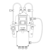
Figure 4: Recommended plumbing for the instrument
1 Feed tubing connection
2 Shutoff clamp
3 Feed tubing connection
4 Backpressure valve
5 Feed tubing connection
6 Drain tubing connection
7 Backpressure valve
8 Drain tubing connection
9 Drain vent
10 Drain tubing connection
11 Sensor connection cable
12 Insert
13 Tubing (not supplied)
14 Nut
The instrument is equipped to be plumbed using 4.75 mm (3/16”) ID, 8 mm (5/16”) OD flexible tubing.
Opaque tubing should be used if the tubing will be exposed to sunlight, to prevent algae growth. For
connectiong we recommend the conection set with quick connector (A-Set-DW, siehe section 11).
In figure 4, there are three flow devices shown. On the inlet side there is a shutoff clamp (Pos. 2) used
during cuvette maintenance, and the flow controller (Pos. 4). With the backpressure valve (Pos. 7) a
back pressure is created in the cell. Backpressure may be required to prevent air from coming out of
solution, which may be observed as tiny air bubbles.