Installation and commissioning Turb 2000 Series
14 ba75695e03 10/2013
14
5
6
7
8
2
3
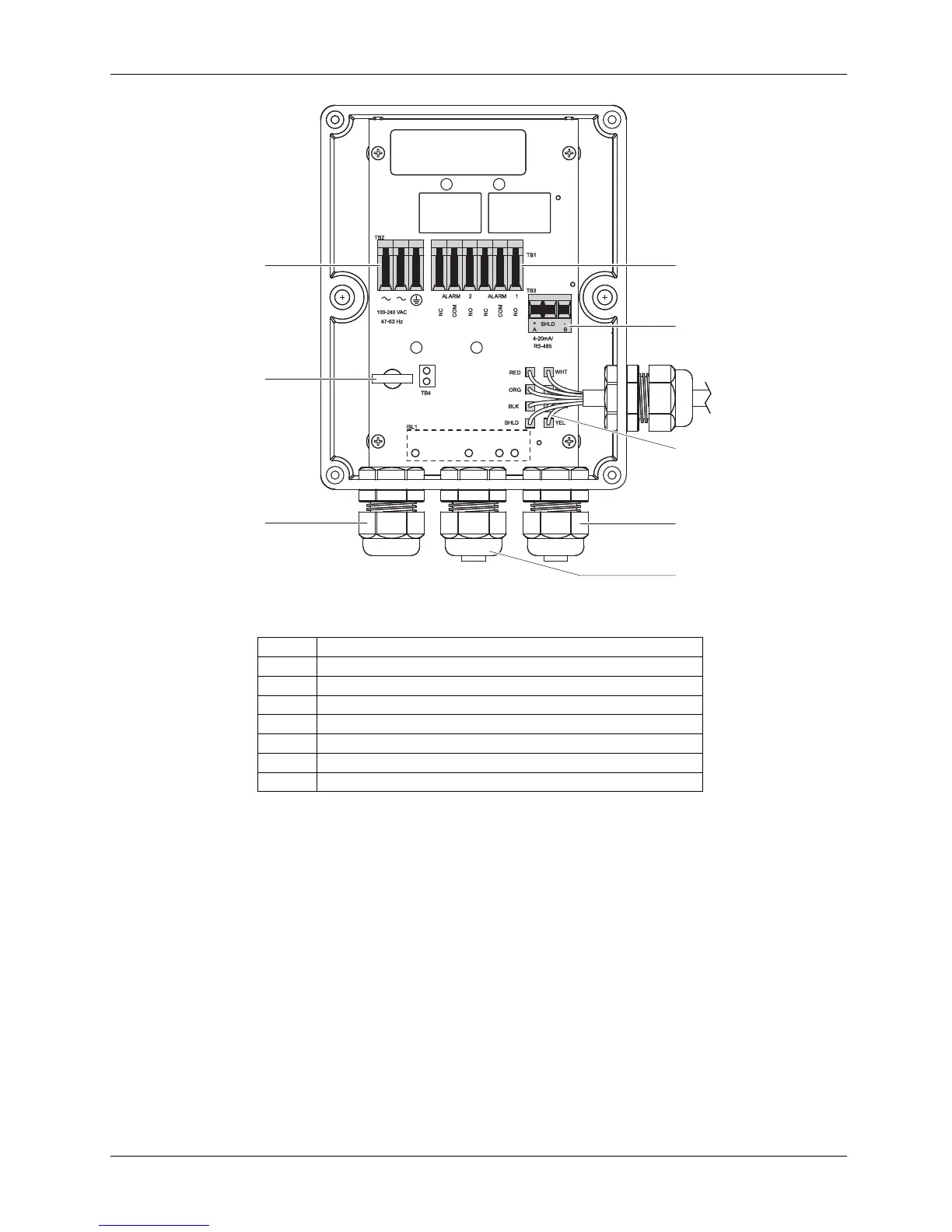
Figure 5: Electrical connections for the instrument
1 Power supply terminal block
2 Power cable strain relief
3 Power cable bulkhead
4 Alarms terminal block 240 V AC, 2A
5 4 – 20 mA / RS485 plug with screw terminals
6 Sensor wiring
7 4 – 20 mA / RS485 bulkhead
8 Alarm cable bulkhead
2.3.1 Power supply
Follow the safety instructions at the beginning of this section. Figure 5 shows the connections to be
made. The scope of delivery does not include a power cable. If the instrument is to be used in the U.S.
or Canada, the power cord must be UL Listed & CSA Certified. Please consult all local electrical codes
for proper connection.
The terminal block is marked as follows: ~ for Neutral and Line, the third symbol indicates a secure
earth ground. The green removable terminal block is suitable for wires 0.82 to 3.3 mm² (18 to 12 AWG).
Run the power cable through the strain relief and connect the wires to the terminal block. Then tighten
the strain relief. The instrument is switched on by switching on the power.