FLEXCOMM 2000
(P-2000/C-2000/RT-2000)
INSTALLATION MANUAL
Publication No. 150-049106 Page 1 of 56
Rev. F P-2000 Installation Manual
Nov 2007
SECTION 1 – GENERAL INFORMATION
1. Introduction
This section contains information relative to the physical, mechanical, and electrical characteristics of the
Wulfsberg Electronics Flexcomm™ “2000” Family of Communications Systems.
2. Applicability
This manual applies only to the P-2000 panel mount transceiver, C-2000 control unit, and RT-2000
remote mount transceiver.
3. Equipment Description
The Wulfsberg “2000” Family FM Communications System is a dual transceiver FM voice
communications designed for aircraft applications. All components of the Flexcomm “2000” Family are
nonessential, ancillary radio transceivers or control units and do not adversely affect flight safety.
The “2000” Family consists of the P-2000 panel mount transceiver and C-2000/RT-2000 control and
remote mount transceiver.
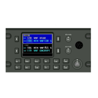
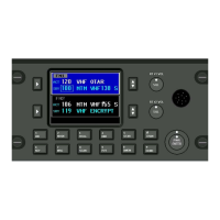
A. P-2000 Panel Mount FM Communications Transceiver
The Wulfsberg P-2000 is a FM Tactical transceiver that incorporates one or two transceiver modules
and control functions into a single panel mount unit. Part number variations of the unit exist for any
combination of the following frequency bands: 137-174 MHz, 380-470 MHz, 403-470 MHz, 450-520
MHz, 764-870 MHz and 806-870 MHz. Each transceiver module with the exception of the 806-870
MHz and 764-870 MHz band can transmit with 1 or 10 Watts transmit power. The 800 MHz units
produce 1 and 2.75 watts transmit power. The P-2000 can operate by itself or in conjunction with the
C-2000 control display acting as a remote slave control. Input voltage is 28 volts DC and the keypad
is backlit from either 28 Vdc,
5 Vdc or 5 VRMS AC.
The P-2000 transceiver is designed to be mounted in the instrument panel that will fit a standard
DZUS mounting. Two connectors, a DB-25 and DB-15 accept all harness wiring on the rear of the P-
2000, while two TNC type RF connector provides the antenna connection through conventional
coaxial cables. For models containing one transceiver, only one antenna port is provided.
The P-2000 consists of functional subassemblies interconnected via standard connectors and ribbon
cables. The case of the P-2000 is designed to be disassembled easily to expose most subassemblies
or circuit modules for service. All adjustments to audio levels can be made via software and do not
require the disassembly of the box. Internal test points are exposed and available to the service
technician without having to remove circuit module subassemblies or use extender cables or cards.
These commodities, technology or software are controlled in accordance with the United States Export Administration Regulations, Export Classification
Control Number (ECCN) 7E994. When exporting, diversion contrary to U.S. law is prohibited.