FLEXCOMM 2000
(P-2000/C-2000/RT-2000)
INSTALLATION MANUAL
Publication No. 150-049106 Page 53 of 56
Rev. F P-2000 Installation Manual
Nov 2007
SECTION 5 – CONTINUED AIRWORTHINESS INSTRUCTIONS
1. Introduction
This document contains instructions for testing a Flexcomm 2000 system on a periodic maintenance cycle
to assure continuous airworthiness. This document is intended to supplement the individual installation
and user manuals of the Flexcomm 2000 system components. The aircraft maintenance personnel
should be in possession of and refer to these manuals during inspections. The Flexcomm 2000 system
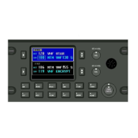
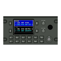
includes a P-2000 panel mount transceiver or a C-2000 control head and a RT-2000 remote mount
transceiver and suitable antennas. The recommended maintenance cycle is one year.
2. Equipment
To perform the checkout procedures described below, you must have the following:
• A Communications Service Monitor or equivalent to transmit and receive over the programmed
frequencies.
• An AT-150 or equivalent broad band antenna or single band antennas covering the same frequencies
of the unit under test.
• Miscellaneous cables and adapters.
• A mic/headset interfaced to the Flexcomm 2000 system.
• Four wire Ohmmeter.
NOTE: Calibration or internal LRU adjustments are only required on a failure condition of the equipment
under test.
3. Antenna Verification
The bonding of all antennas and the radio chassis to the airframe should be verified to have an
impedance of less than 5 mOhm. The VSWR of the combined antenna and coax cable should be
measured at the connector to the radio. The VSWR should be no more than the maximum specified
antenna 2.5:1.
A. Transmitter Verification
(1) Select a channel with known RX and TX frequencies on FM1.
(2) Set the Service Monitor to Rx the TX frequency of the selected channel. Connect the output
of the radio under test to the Service Monitor RF input port with a cable less than three feet
in length (refer to the Service Monitor User’s Manual).
(3) Use the handset interfaced to the Flexcomm 2000 system to TX a signal, modulated from
the Service Monitor.
(4) Measure the output power, output frequency, and FM modulation (kHz deviation) with the
Service Monitor. Verify that the output frequency and power are within specification. Adjust
or repair as necessary.
(5) Repeat for FM2 transceiver.
These commodities, technology or software are controlled in accordance with the United States Export Administration Regulations, Export Classification
Control Number (ECCN) 7E994. When exporting, diversion contrary to U.S. law is prohibited.