FLEXCOMM 2000
(P-2000/C-2000/RT-2000)
Installation Manual
Page 16 of 56 Publication No. 150-049106
P-2000 Installation Manual Rev. F
Nov 2007
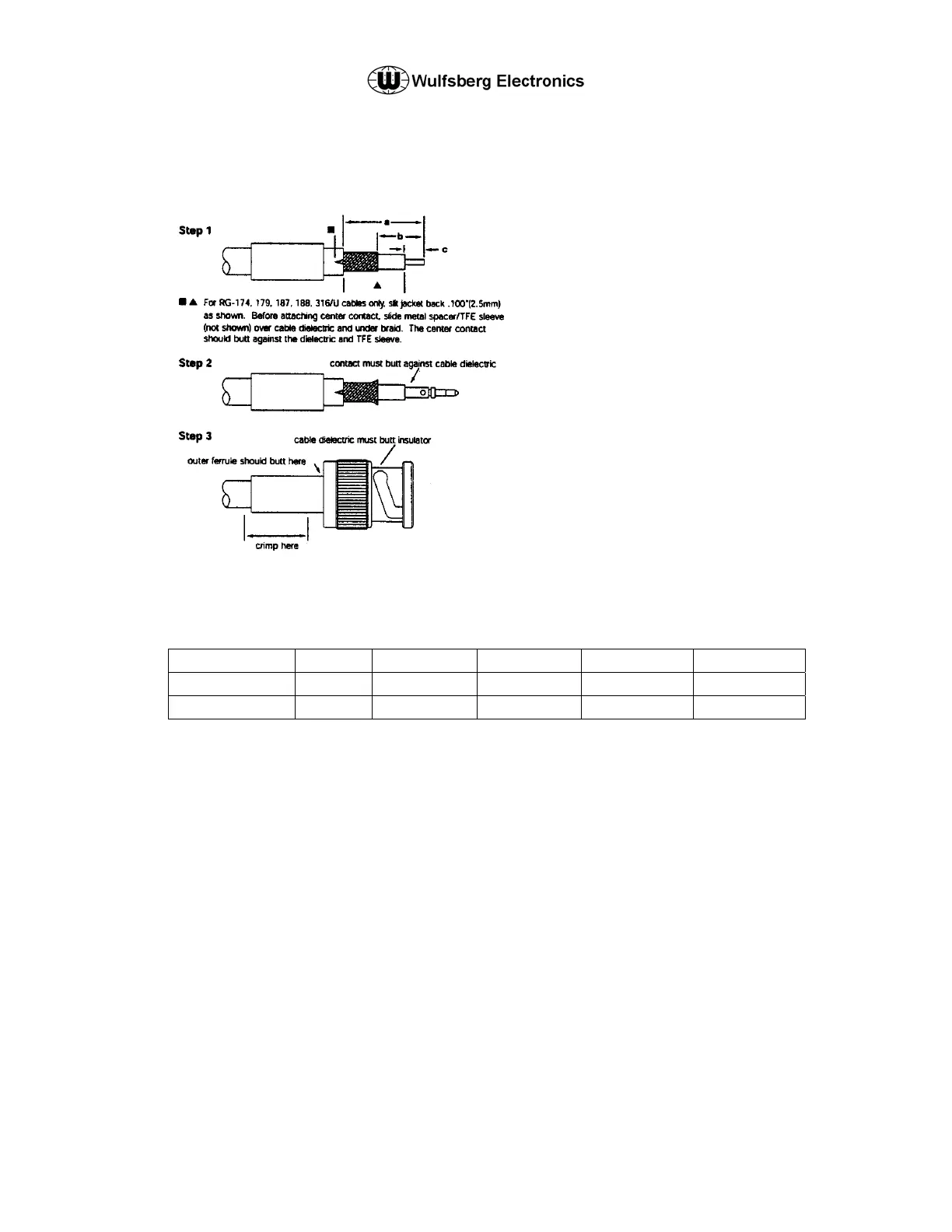
(2) BNC Connectors
Step 1 Strip cable jacket. braid, and dielectric to
dimensions in table below. (for
RG-62,71,210/U cable, trim an additional
.039"(1.0mm) of insulation off center
conductor and add bushing] All cuts are
to be sharp and square. Important: Do
not nick braid, dielectric, and center
conductor. Slide outer ferrule onto cable
as shown.
Step 2 Flare slightly end of cable braid as shown
to facilitate insertion of inner ferrule.
Important: Do not comb out braid. Place
contact on cable center conductor so that
it butts against cable dielectric. Crimp
contact in place.
Step 3 Install cable assembly into body
assembly so that inner ferrule portion
slides under braid. Push cable assembly
forward until contact snaps into place in
insulator. Slide outer ferrule over braid
and up against connector body. Crimp
outer ferrule.
* for pneumatic crimp tool 227-60, use die sets
indicated in this column
Wulfsberg P/N Straight Right Angle a = b = c =
129-049080-01 X .593(15.1) .250(6.4) .146(4.0)
129-049081-01 X .578(14.6) .328(8.3) .125(3.1)
These commodities, technology or software are controlled in accordance with the United States Export Administration Regulations, Export Classification
Control Number (ECCN) 7E994. When exporting, diversion contrary to U.S. law is prohibited.