To prevent possible overloading, each vibrator must have its own motor
protection switch, the tripping current of which must be set in accordance with
the data on the nameplate.
If there are two, counter rotating motors running, it must be ensured that if one
motor fails, both motors switch off at the same time
(see circuit diagram on page 45).
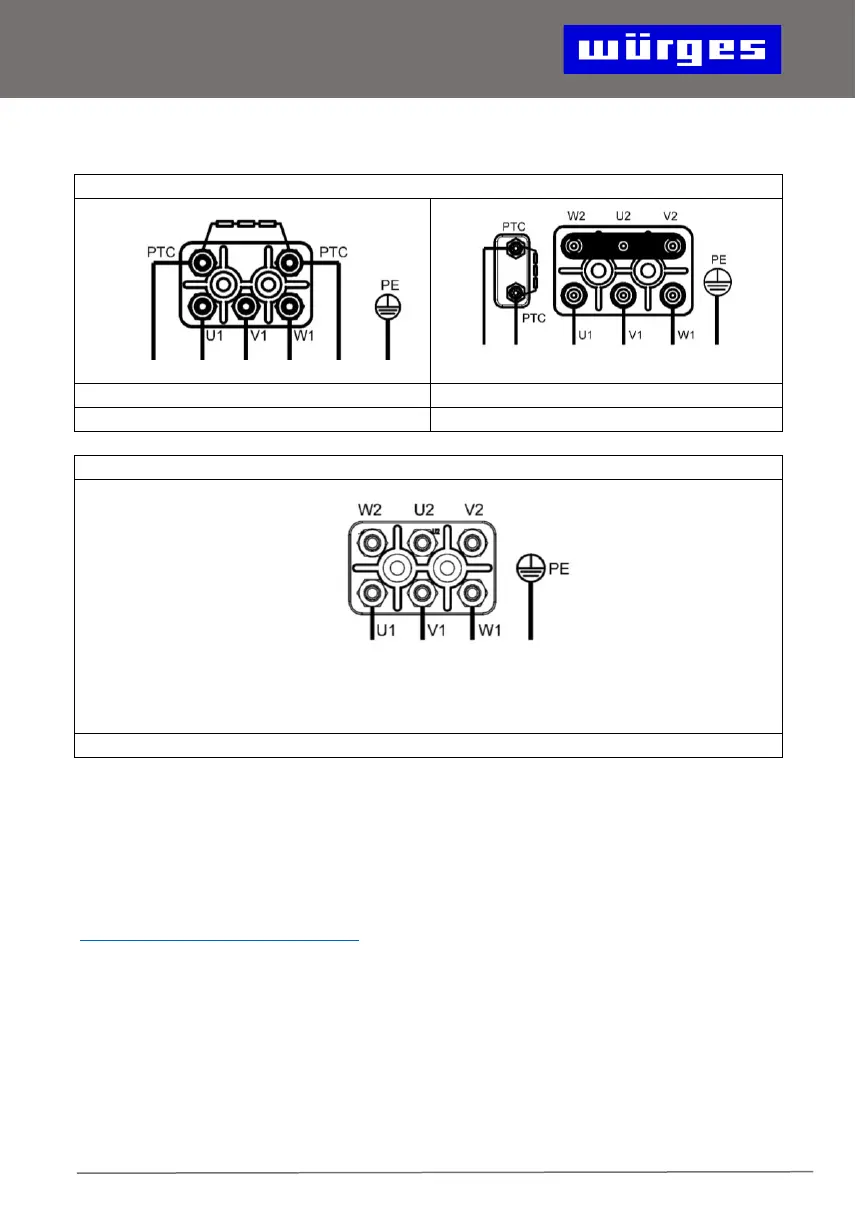
Only flexible cables may be used for connection. We recommend the following
cable types:
HV 0,4 - HV 1: H 05 RN-F 4G0,75²
HV 2 - HV 85: H 07 RN-F 4G1,5²
from HV 75: NSHTÖU-J 4G1,5² (or H 07 RN-F 4G1,5²)
HV 2 GL: H 07 BQ-F 2x2,5²
HF: H 07 RN-F 4G1,5²