12
2.0 INSTALLATION
©2000 Xantrex Technology Inc.
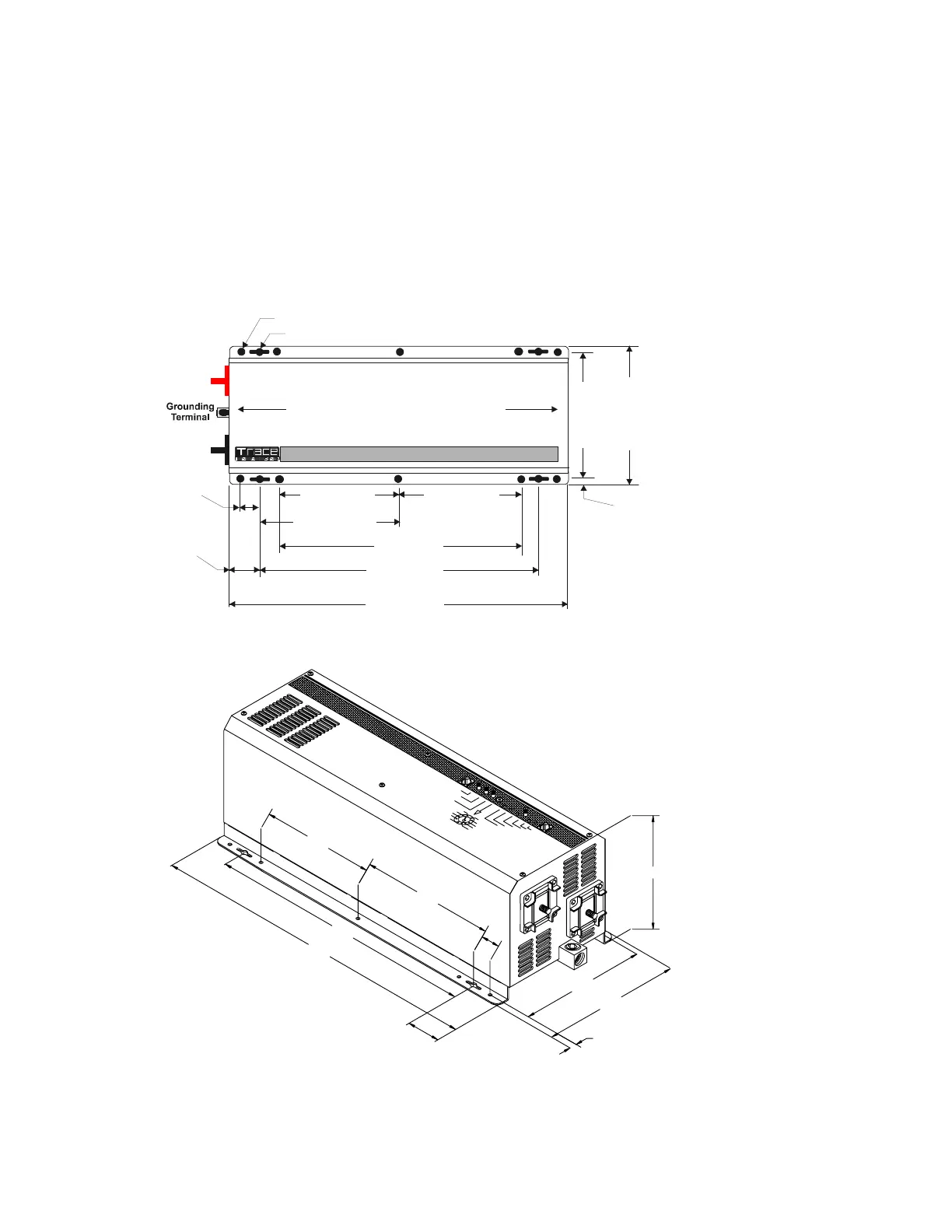
Figure 8
Dimensional Drawings for Screw Hole Placement
Referring to Figure 8, drill out the mounting hole locations for the inverter.
With assistance, lift the inverter into position and install it onto the 2 x 4s using 1/4 x 1-1/2
inch lag bolts and washers.
Alternatively, a half or quarter sheet of 3/4 inch plywood can also be used as a backing, with the
inverter mounted directly to the plywood using 1/4 inch diameter lag bolts and washers. The plywood
must span three studs for adequate support.
20.175 inches
51.244 cm
1.90 inches
4.83 cm
7.00 inches
17.8 cm
7.00 inches
17.8 cm
16.00 inches
40.64 cm
14.00 inches
35.56 cm
8.00 inches
20.32 cm
7.640 inches
19.40 cm
8.370 inches
21.25 cm
+
TERMINAL
–
TERMINAL
1.00 inches
2.54 cm
0.365 inche
0.93 cm
DC SIDE
AC SIDE
0.375 DIA 4 PLACES
0.281 DIA 10 PLACES
975-0012-D-011
T
R
A
C
E
E
N
G
I
N
E
E
R
I
N
G
T
R
A
C
E
E
N
G
I
N
E
E
R
I
N
G
7.640
8.370
0.365
20.175
16.00
6.970
1.900
1.00
8.00
7.00
.375 DIA. 2 PLACES
.281 DIA. 5 PLACES
975-0012-D-012
 Loading...