5.0 APPENDIX
67
©2000 Xantrex Technology Inc.
Neutral
Ground
Black–Hot
Single White–Neutral
Bare–Ground
120 VAC
120 VAC
25 A
50 A
25 A
25 A
Breaker
(Ganged)
Red–Hot
Load Center
062949-003
25 A
White–Neutral
Splice
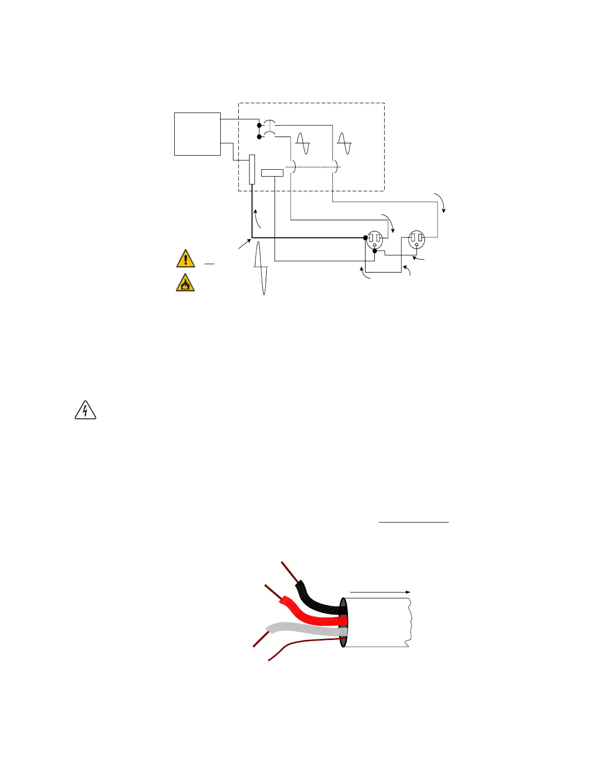
The in-phase currents
a
dd at this point
exceeding wire
capacity!
25 A
Breaker
(Ganged)
Bare–Ground
Splice
120 VAC
Inverter
(or generator)
Figure 51
120 VAC Inverter Incorrectly Wired in a Multiwire Branch Circuit
Identifying Multiwire Branch Circuits
WARNING: THE NEXT STEP INVOLVES OPENING THE LOAD CENTER EXPOSING LIVE
CIRCUITS. THIS PROCEDURE SHOULD ONLY BE PERFORMED BY QUALIFIED PERSONS OR
ELECTRICIANS.
Multiwire branch circuits can be identified by removing the cover on the load center and
inspecting the wiring. Conventional 120 VAC circuits are identified by a 2-wire-plus-ground (black,
white and copper) romex for each circuit. Multiwire branch circuits use a 3-wire-plus-ground
arrangement (black, red, white and copper) for each circuit run (Figure 49).
If this arrangement exists in the panel and it is being powered by a stand-alone 120 VAC
inverter, a potential fire hazard exists! For safety, these circuits must be rewired to meet code.
Black
From L1
Breaker
Single Neutral
White
Ground
Bare Copper
To Branch Circuits
Red
From L2
Breaker
062949-005
Figure 52
Multiwire Branch Circuit Wiring
Multiwire Branch Circuits (continued)
 Loading...