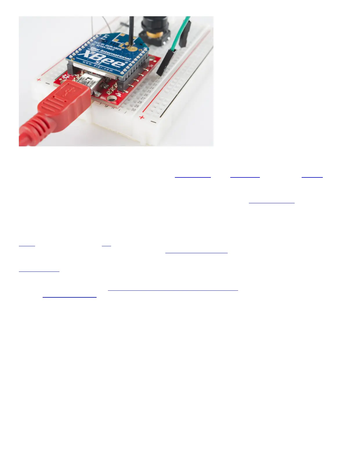
The XBee Explorer can be used with a USB cable and breadboard concurrently -- just solder some headers into the breakout pins.
(Actually solder them, don't pretend like we did in the image above.)
If male headers don't fit your purpose, you can alternatively solder in female headers (to plug jumper wires into), or even just bare wire.
Just make sure you don't solder anything into the top side of the board -- or you may be unable to plug the XBee in!
Tip: We won't cover it in this tutorial, but those "DIO#" pins can be configured as either inputs or outputs. That means you can use an
XBee to directly drive LEDs or motors, and read analog sensors or buttons. Just make sure to use a logic level converter or transistor
when using the pins for I/O line passing. More information about configuring the pins for I/O line passing can be found in the XBee's user
manual.
Starting With X-CTU
X-CTU is free software, provided by Digi (the manufacturer of XBee), which we use to configure and manage XBees, and test XBee
networks. If you haven't already, head over to their website and download the latest release and follow their instructions to install the
software.
Download X-CTU
Tip: The latest XBee Series 3 has enhanced features including new AT commands, Bluetooth, and MicroPython. While MicroPython is
available for the XBee Series 3, not all MicroPython modules are available for the XBee Series 3. For more information, make sure to
check the support documentation.
Adding XBee's
Before continuing on, make sure you've plugged an XBee (correctly) into your Explorer, and have the Explorer plugged into your
computer. When you installed the drivers for your Explorer it should have been assigned port number. You'll need that shortly.
After initially opening X-CTU, you'll be presented with a window like this: