XT-50, XT-80, and XT-100 Amplifiers Installation 2-5
Control and Monitor Interfaces
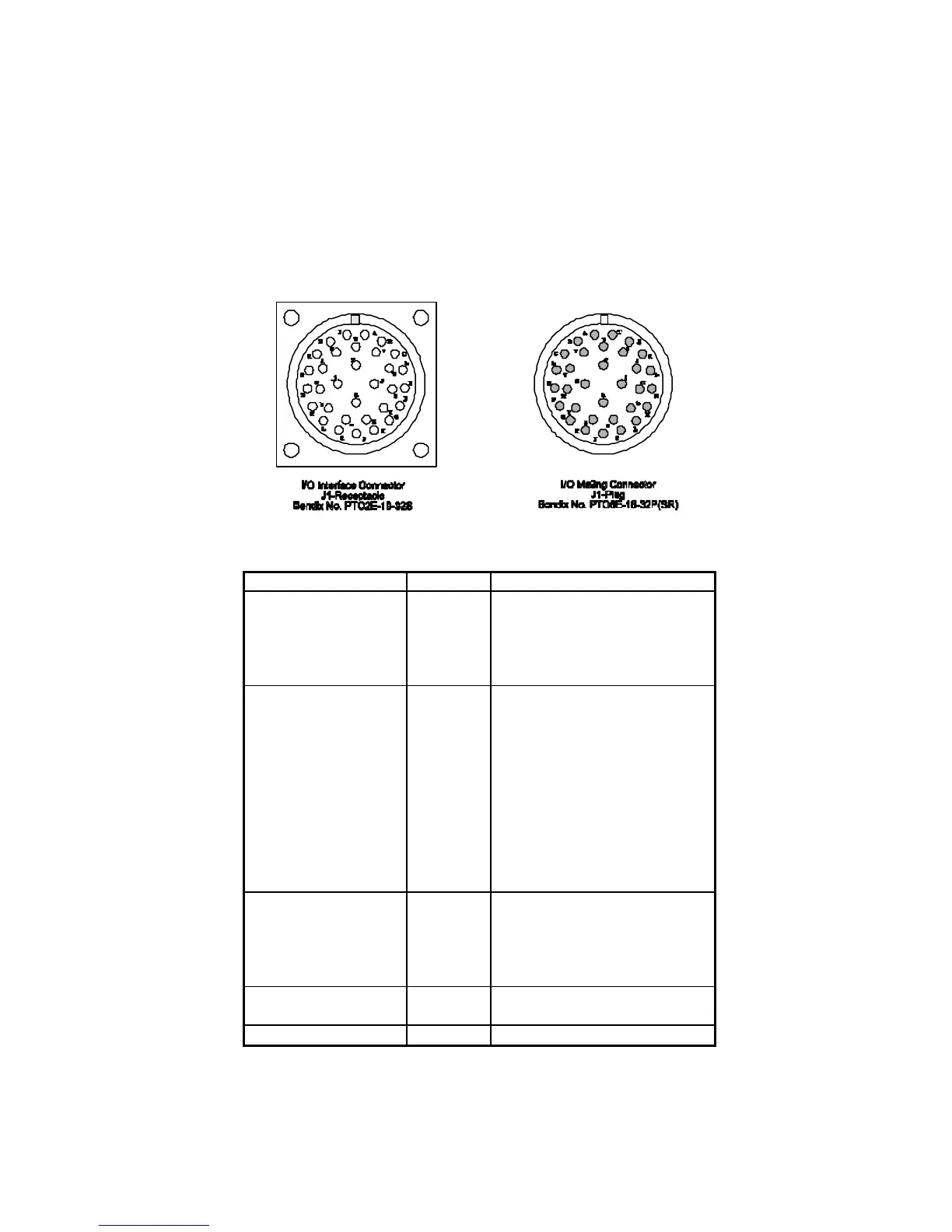
The control interface connector (J1) pinouts are shown in Figure 2-8. There are five classes of
interfaces:
• Controls • Analog Signals
• Digital Status • DC Bias Voltages
• External Voltage
Item Pin Functions
Controls
(Commands)
All circuits
active low
a
F
J
X
Z
AC Power ON
High Voltage ON
Heater Standby
Fault Reset
AC Command Return
Status, Digital
(Indicators)
All circuits
active low.
A
C
G
H
K
M
R
S
T
U
W
Helix/Arc Fault Latched
Helix/Arc /Fault
Heater Timer Complete
TWT Temperature Fault
High Voltage ON
Fan ON
High Voltage Fault
Fan ON High
Summary Fault
Fan Lock
Control/Status Return
Signals, Analog b
D
L
N
P
RF Output Power
Helix Current
High Voltage Monitor
Analog Signal Return
TWT Temperature
Output Voltages E
V
+15 VDC (100 mA maximum)
+24 VDC (100 mA maximum)
External Voltage Y External Supply (+5/15 VDC)
Figure 2-8. Interface Connector Pinouts