XT-50, XT-80, and XT-100 Amplifiers Installation 2-9
The control functions shown in Figures 2-9 and 2-10 are:
AC ON Control: This circuit inhibits operation of the power amplifier
power supply when pin J1-a is high. When pin J1-a is connected to pin
J1-Z, power supply operation is enabled.
WARNING: THE AC CONTROL CIRCUIT DOES NOT AFFECT THE
CONNECTION OF THE POWER AMPLIFIER TO PRIME POWER.
DISCONNECT PRIME POWER WHEN YOU SERVICE THE POWER
AMPLIFER.
High Voltage ON, Heater Standby ON and Fault Reset Control: These circuits
are isolated from the internal circuits of the power amplifier. The
operation of all three control circuits is the same. When pins F, J , or X are
pulled to the power amplifier ground (pin J1-W), the control function is
enabled. Fault Reset should be implemented with a momentary circuit or
switch.
Digital Status Circuits
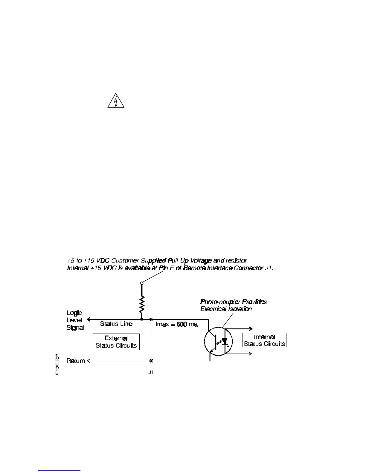
The digital status interface circuits are isolated outputs as shown in Figure 2-11. The internal +15
VDC supply (100 mA max) or an external supply can be used to bias the digital status indicator
circuits. Refer to Figure 2-8 for indicator circuit pinout designations and the text following Figure 2-
11 for indicator circuit descriptions.
Figure 2-11. Digital Status Circuit Isolation


 To Next Page