AC701 Getting Started Guide www.xilinx.com 25
UG967 (v3.0) July 10, 2013
Advanced Bring-up with Base Targeted Reference Design
4. Check the status of the design using the AC701 board LEDs. The design provides
status with the GPIO LEDs located on the upper right portion of the AC701 board.
When the PC is powered on and the TRD has successfully configured, the LED status
from left to right indicates:
• LED position 1: ON if DDR3 is calibrated
• LED position 2: Heart beat LED, flashes if PCIe user clock is present
• LED position 3: ON if the lane width is x4, else flashing
• LED position 4: ON if the PCIe link is up
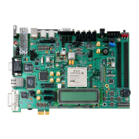
Figure 18 shows the location of the status LEDs.
X-Ref Target - Figure 18
Figure 18: GPIO LEDs Indicating TRD Status
UG967_18_121812
LED Position 1 2 3 4

 Loading...


