VCU1525 Acceleration Platform User Guide 10
UG1268 (v1.0) November 13, 2017 www.xilinx.com
Chapter 2
Board Setup and Configuration
Board Component Location
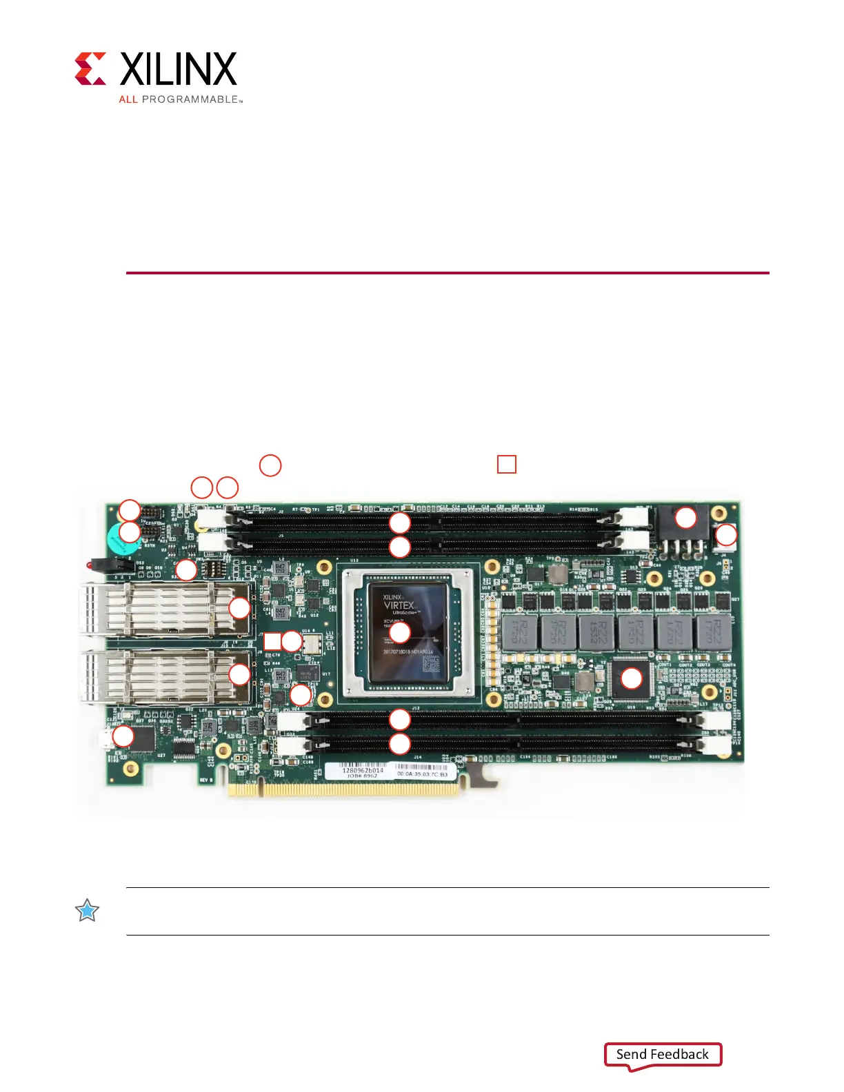
Figure 2-1 shows the location of components on the VCU1525 board. Each component
shown is keyed to Table 2-1. Table 2-1 identifies the components, references the respective
schematic page numbers, and links to a detailed functional description of the component
and board features in Chapter 3, Board Component Descriptions.
IMPORTANT: Figure 2-1 is for visual reference only and might not reflect the current revision of the
board.
X-Ref Target - Figure 2-1
Figure 2-1: VCU1525 Board Components
00
Round callout references a component
on the front side of the board
Square callout references a component
on the back side of the board
00
1
2
3
4
5
16
17
8
9
19 20
18
13
14
7
12
12
6
15
This photo is for visual reference only and might not reflect the current revision of the board.
X19972-111017