VCU1525 Acceleration Platform User Guide 37
UG1268 (v1.0) November 13, 2017 www.xilinx.com
Chapter 3: Board Component Descriptions
Status LEDs
The VCU1525 board is designed to operate with the heat sink and fan enclosure cover
installed. Status light emitting diode (LED) DS3 is a triple-stack LED which is visible through
a cut-out in the PCIe end bracket.
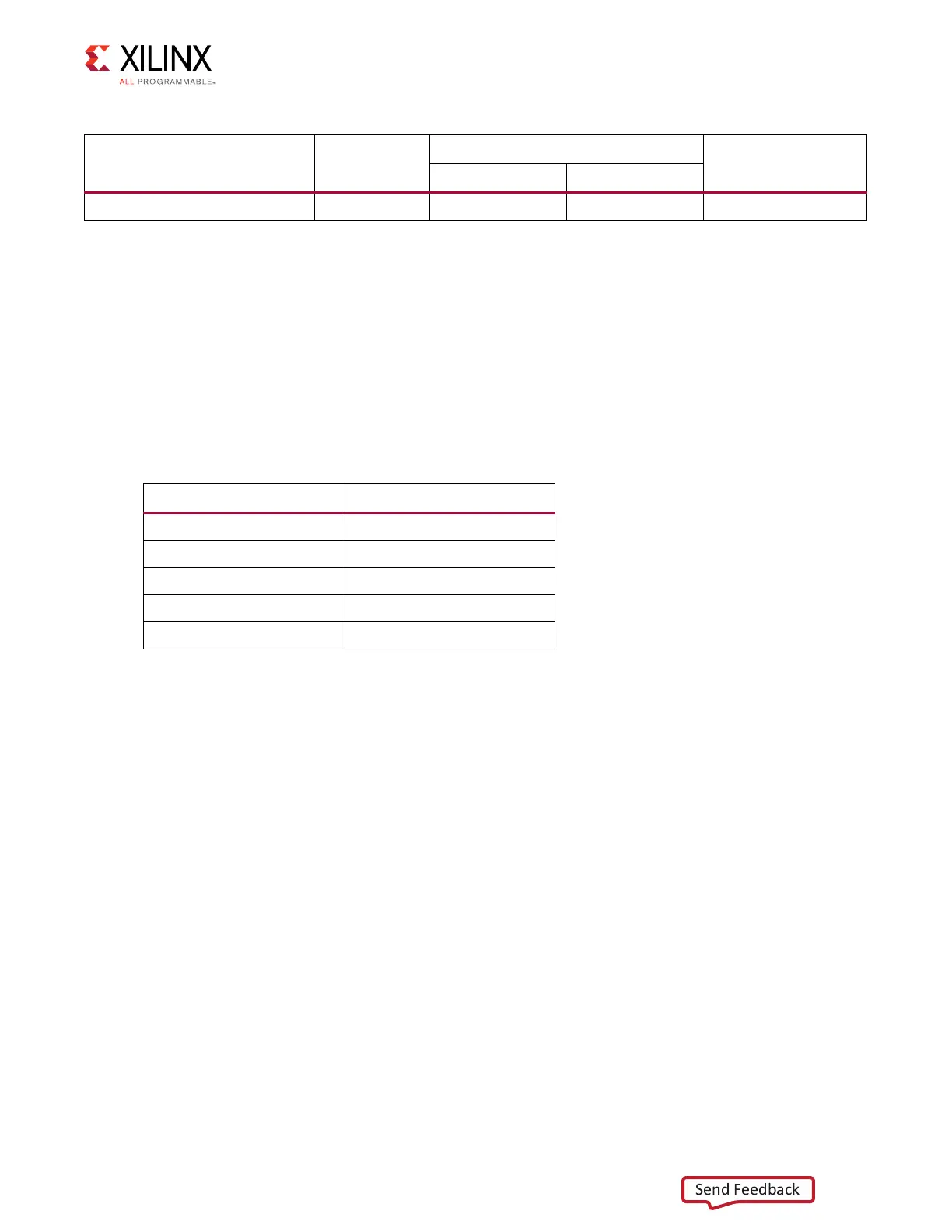
Table 3-7 defines VCU1525 board status LEDs.
User I/O
[Figure 2-1, callout 18]
The VCU1525 board provides these user and general purpose I/O capabilities:
• 4-position active-Low user DIP switch (callout 18) USER_SW_DP[0:3]: SW3
• DIP switch SW3 (not populated on VCU1525 revision D and later boards)
The FPGA connections for the GPIO are listed in Appendix A, Master Constraints File Listing.
Board Management Controller
[Figure 2-1, callout 15]
The VCU1525 hosts an MSP432P401RIPZ board management controller (BMC) U19
comprising a MSP432 ARM® Cortex® microcontroller with integrated ADCs and GPIO for
control, monitoring, and sideband communication with the host system and FPGA.
For MSP432 functional block diagram details, see Figure 1-1. MSP432P401M Functional
Block Diagram in the MSP432P401M data sheet at the Texas Instruments website [Ref 8].
I2C_FPGA_SDA/SCL
(1)
3 Various Various U28 PCA9546
Notes:
1. This connection allows the MSP432 U19 to access the U28 switch target devices and FPGA U13.
Table 3-6: I2C_MAIN_SDA/SCL I2C Bus Addresses (MSP432 U19 only) (Cont ’d)
I2C Bus
I2C Switch
Position
I2C Address
Device
Binary Format Hex Format
Table 3-7: VCU1525 Board Status LEDs
Reference Designator Description
DS1 RED: POWER_GOOD
DS2 BLUE: DONE_0
DS3 RED: STATUS_LED0
DS3 YELLOW: STATUS_LED1
DS3 GREEN: STATUS_LED2