XO 4 & XO FLEX TROUBLE SHOOTING GUIDE
Version 3.30 23
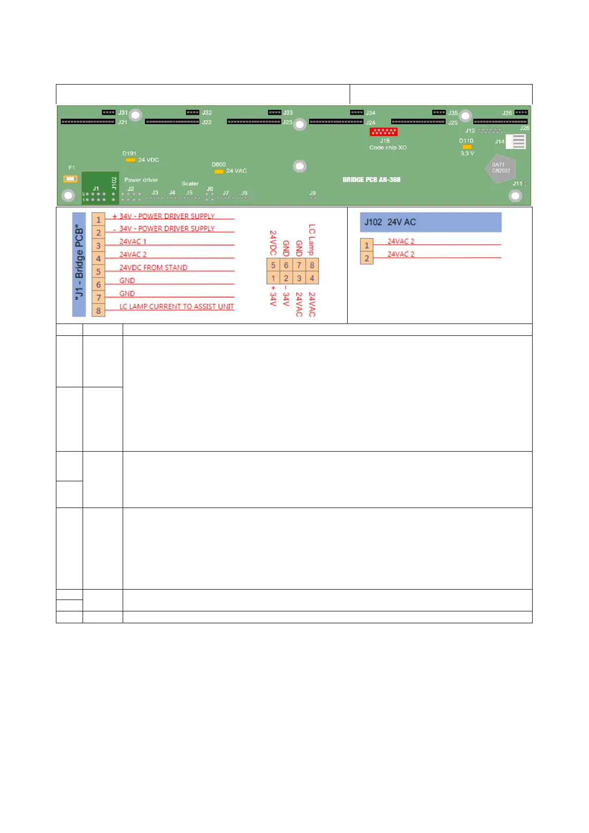
BRIDGE PCB - CONNECTORS J1 – J102
Point of measurement
1 +34V
There is no indicator LED for +34V and -34V on “Bridge PCB AN-368”.
The indicator LEDs are in the terminal on the “Power Supply PCB AN-371”. LEDs D2 & D4
indicate the presence of -34 and +34V before modulation. for more information, please
refer to chapter “Power Supply PCB AN-371”.
These voltages are distributed on the “power driver AO-137” and are used for the rotation
of the MC3 micromotor and the functionality of the curing lamp.
If the fuses burn directly when the unit is switched on, always check that the cable CA-
004 is not damaged first.
+34V is measured between pin 1 and 6.
-34V is measured between pin 2 and 6
2 -34V
3
24VAC
The LED D800 located on the "Bridge PCB AN-368" indicates the presence of 24VAC.
instruments on 24AC
- Scaler
- Syringe
4
5 24VDC
The LED D191 located on the “Bridge PCB AN-368” indicates the presence of 24VDC.
Fuse F1 protects the 24VDC, always check the condition of the fuse.
The 24VDC is modulated on the “Power Supply PCB AN-371”.
On “Power Supply PCB”, LED D6 indicates that the 24VDC is available.
The +34V is measured between pin 1 and 6 or 7.
If the fuses F1 continue to blow, measure the resistance of the solenoid valves for any
GND
0V
8