XO 4 & XO FLEX TROUBLE SHOOTING GUIDE
Version 3.30 22
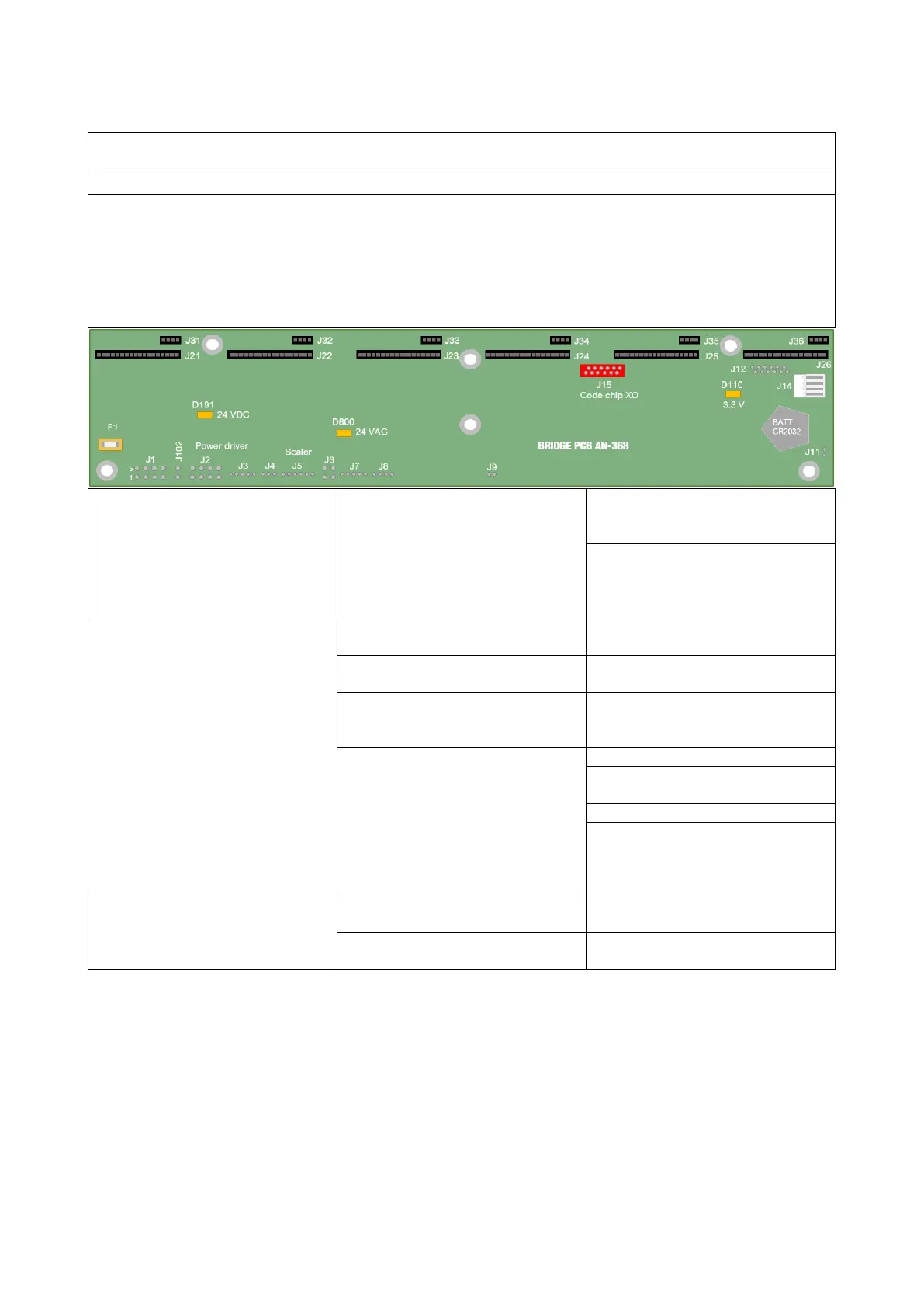
The “bridge PCB AN-368” is the XO 4 Unit's mainboard, controls all functions of the Unit. Internal
communication with peripherals is established via an RS-485 communication BUS. A computer can be
connected to the Unit via the serial port located behind the stand. Communication between the “Bridge
PCB AN-368” and the computer is established via an RS-432 chipset. It can be used for updates,
maintenance and uploading or backing up the unit configuration. The Unit's firmware is uploaded in a
flash RAM . The 24 VDC and the 24 AC are generated on the “
Power Supply PCB AN-371” located in the
stand. The 5 VDC and 3.3 VDC are generated by a chipset located on the Bridge PCB.
No power supply from the UNIT
24VAC
The Precisions voltage is
generated from the “Power
Check that the CA-004 power
cable is properly connected on
J1 “Bridge PCB AN-368” to
J31 “Backplane PCB AN-371”.
Fuse F1 on Bridge PCB is blown
Replace fuse F1,
(Nano 3A part no. ML-601)
No power supply from Unit
24VDC
Check that the CA-004 power
cable is properly connected
On the “Power supply PCB AN-
371”
Check LED D6 (5,12, 24VDC)
is lid. Refer to Power supply PCB
“Bridge PCB AN-368”
Measure the 24VDC on J1 pins 5
(24VDC) and 6 (GND).
If the fuse continues to blow,
check for short circuit on the
valves in the instrument bridge
(3.3VDC is generated from
5VDC on the Bridge PCB)
No power supply from Unit
24VDC.
Verify that 24VDC is available
(LED D191 24VDC is ON).
If 24VDC is available, replace
Bridge PCB.